Examples and tips
PROGRAMMING MANUAL 276
Revision 1.0
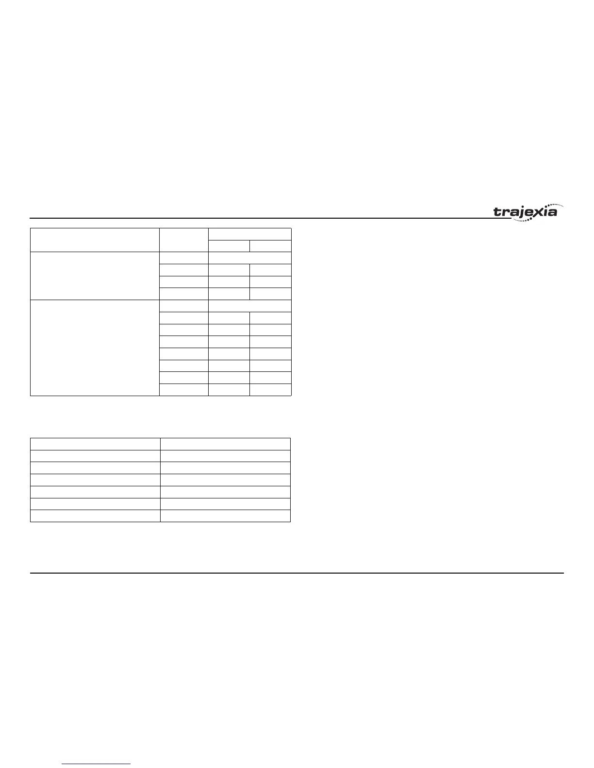
For the Junma Servo Driver, all input signals are mapped to a fixed location
on the CN1 I/O connector. The table below shows the input signals and pin
numbers.
/i
For the G-Series Servo Driver, all input signals are mapped to a fixed
location on the CN1 I/O connector. The table below shows the input signals
and pin numbers.
/BRK (active low) - Pn50F.2 0 Always OFF
1251
22723
32925
IO12 - Pn81E.0
IO13 - Pn81E.1
IO14 - Pn81E.2
IO15 - Pn81E.3
0Always OFF
1 40 (SI0) 13 (SI0)
2 41 (SI1) 7 (SI1)
3 42 (SI2) 8 (SI2)
4 43 (SI3) 9 (SI3)
5 44 (SI4) 10 (SI4)
6 45 (SI5) 11 (SI5)
7 46 (SI6) 12 (SI6)
Input signal - Parameter name Parameter
setting
CN1 pin number
Sigma-II Sigma-V
Input signal CN1 pin number
P_OT (active high) 4
N_OT (active high) 3
DEC (active low) 1
EXT1 (active low) 2
BRK (active low) 13
E-STP (active high) 6