15
CIDRW System
User’s Manual
SECTION 1
Component Names and Functions
SECTION 1
Product Outline
Component Names and Functions
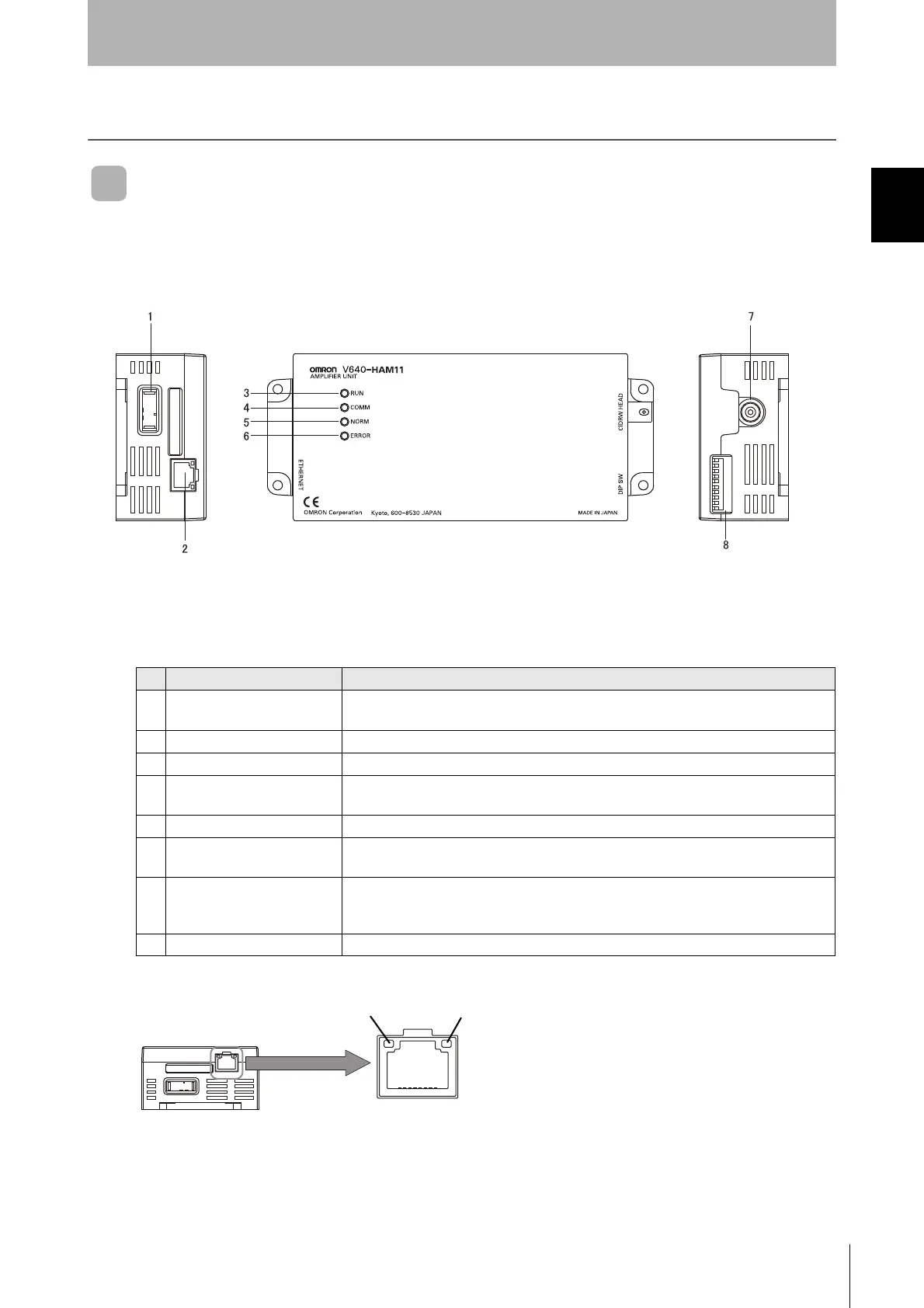
V640-HAM11-ETN-V2 and V640-HAM11-L-ETN-V2 Amplifier Units
No. Name Function
1 Dedicated power supply con-
nector
Connect to the 24 VDC power supply.
2 Ethernet port Connect to the host device through a LAN cable.
3 RUN indicator (green) Turns ON when the Amplifier Unit is in normal operation.
4 COMM indicator (yellow) Turns ON during communications with the host device or during communications with an
ID Tag.
5 NORM indicator (green) Turns ON when the communications finish with no error.
6 ERROR indicator (red) Turns ON when an error occurs during communications with the host device, or during
communications with an ID Tag.
7 CIDRW Head connection port A CIDRW Head is connected here.
The V640-HS61 CIDRW Head is used with the V640-HAM11-ETN-V2. The V640-HS62
CIDRW Head is used with the V640-HAM11-L-ETN-V2.
8 Setting DIP switches Set the IP address and enable/disable the Test Mode with this DIP switch.
LINK(green)
ACT(yellow)
LINK---lights while linking normally.
ACT---lights when detects a carrier.
 Loading...