CIDRW System
User’s Manual
SECTION 7
Characteristic Data According to Conditions of Use
SECTION 7
Appendix
81
Characteristic Data According to Conditions of Use
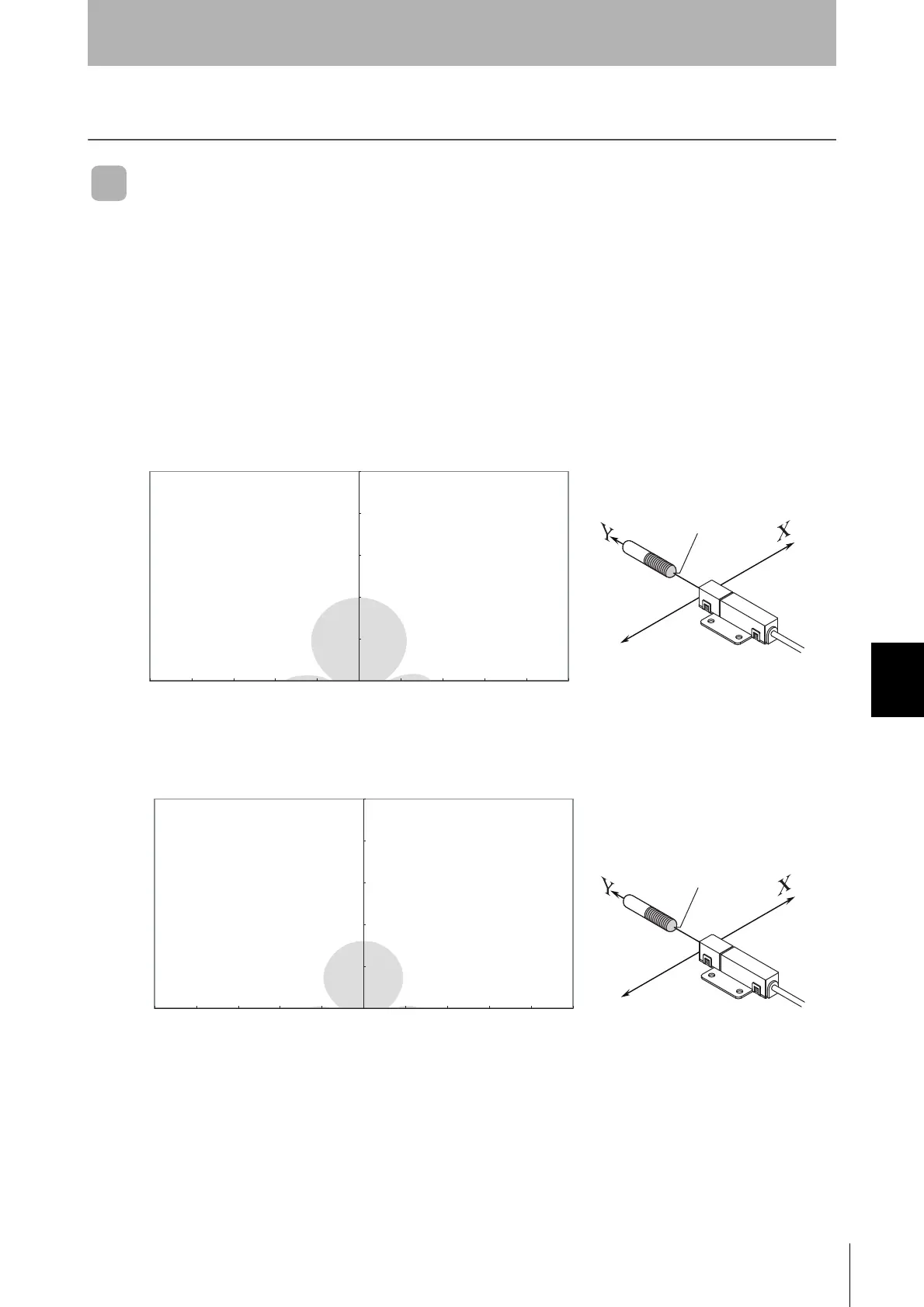
Maps of Communications Areas (Reference Only)
The figures given below for communications areas (communications distances) are reference values
only. The maps of communications areas will vary according to the ID Tags that you use, the back-
ground metals, the ambient noise, the effects of temperature and so on, and should be thoroughly con-
firmed on installation. The direction of the ID Tags will affect communications performance. Check the
direction of the coils in the ID Tags before using the ID Tags.
■ V640-HAM11-ETN-V2
• Coaxial Mounting (RI-TRP-DR2B-30)
• READ
• WRITE
-250 -200 -150 -100 -50 0 50 100 150 200 250
0
50
100
150
200
250
Communications Area (READ)
Distance in Y direction (mm)
Distance in X direction (mm)
Measurement point
-250 -200 -150 -100 -50 0 50 100 150 200 250
0
50
100
150
200
250
Communications Area (WRITE)
Distance in Y direction (mm)
Distance in X direction (mm)
Measurement point
 Loading...