16
SECTION 1
Part Names and Functions
RFID System
User's Manual
SECTION 1
Product Overview
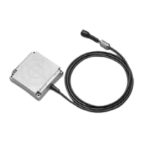
■ Antenna Connector Port
Connects the V680 Series Antenna.
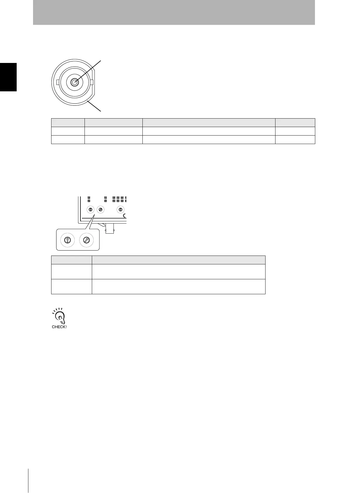
■ Node Address Switches
The node address switches set the FL Remote Node Address. This node address is used as the right-
most part of the IP address (e.g., xx of 192.168.250.xx).
An address error will occur if "00" or "65" to "99" are set.
Turn the power OFF before setting the node address switches. The node address that is set when the power is turned
ON will be valid.
Pin No. Name Description I/O
1 S Signal line ---
2 GND Analog ground ---
Item Description
Setting method Two-digit decimal number
The left rotary switch sets the 10s digit, and the right rotary switch set the 1s digit.
Setting range 01 to 64
The default setting is 01.
OFF
FSM RFID
0
9
8
7
6
5
4
3
2
1
0
9
8
7
6
5
4
3
2
1
0
9
8
7
6
5
4
3
2
1
OMRON Corporation
SOURCE : 24VDC 0.3A
MADE IN JAP
X10
1
X10
0
RMT NORM/ERR 4 3 2 1
NODE No. MODE
0
9
8
7
6
5
4
3
2
1
0
9
8
7
6
5
4
3
2
1
X10
1
X10
0
NODE No.