OIL
SYSTEM
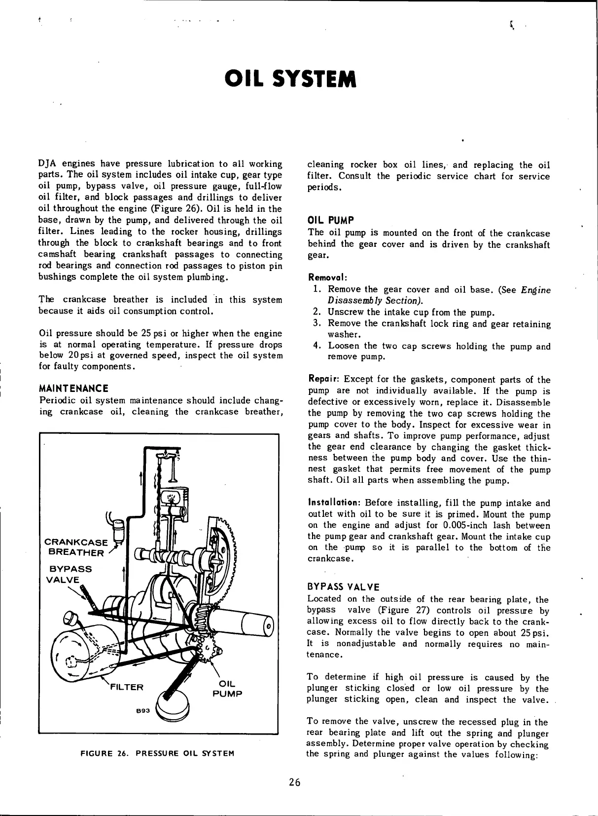
DJA
engines
have
pressure
lubrication to all
working
parts. The oil system includes oil intake cup,
gear
type
oil
pump,
bypass
valve, oil
pressure
gauge,
full-flow
oil
filter,
and block
passages
and
drillings
to deliver
oil
throughout the engine (Figure 26). Oil is held in the
base,
drawn by the pump, and delivered through the oil
filter.
Lines leading to the rocker housing,
drillings
through
the block to crankshaft bearings and to
front
camshaft bearing crankshaft
passages
to connecting
rod
bearings and connection rod
passages
to piston pin
bushings complete the oil system plumbing.
The
crankcase
breather is included in this system
because
it aids oil consumption control.
Oil
pressure
should be 25 psi or higher when the engine
is
at normal operating temperature. If
pressure
drops
below
20psi at governed
speed,
inspect the oil system
for
faulty
components.
MAINTENANCE
Periodic oil system maintenance should include chang-
ing
crankcase
oil, cleaning the
crankcase
breather,
CRANKCASE
BREATHER
BYPASS
VALVE
OIL
PUMP
FIGURE
26.
PRESSURE
OIL
SYSTEM
cleaning rocker box oil lines, and replacing the oil
filter.
Consult the periodic service chart for service
periods.
OIL
PUMP
The oil pump is mounted on the
front
of the
crankcase
behind
the
gear
cover and is driven by the crankshaft
gear.
Removal:
1. Remove
the
gear cover
and oil
base.
(See
Engine
Disassembly Section).
2.
Unscrew the intake cup
from
the pump.
3. Remove the crankshaft
lock
ring
and
gear
retaining
washer.
4.
Loosen the two cap screws holding the pump and
remove pump.
Repair: Except for the
gaskets,
component parts of the
pump are not
individually
available. If the pump is
defective or excessively
worn,
replace it. Disassemble
the pump by removing the two cap screws holding the
pump cover to the body. Inspect for excessive wear in
gears
and shafts. To improve pump performance, adjust
the
gear
end
clearance
by changing the
gasket
thick-
ness
between the pump body and cover. Use the
thin-
nest
gasket
that permits free movement of the pump
shaft. Oil all parts when assembling the pump.
Installation:
Before
installing,
fill
the pump intake and
outlet
with
oil to be
sure
it is primed. Mount the pump
on
the engine and adjust for 0.005-inch lash between
the pump
gear
and crankshaft
gear.
Mount the intake cup
on
the punp so it is parallel to the bottom of the
crankcase.
BYPASS
VALVE
Located
on the outside of the
rear
bearing plate, the
bypass
valve (Figure 27) controls oil
pressure
by
allowing
excess
oil to
flow
directly back to the crank-
case.
Normally
the valve begins to open about 25 psi.
It
is nonadjustable and normally requires no main-
tenance.
To
determine if
high
oil
pressure
is
caused
by the
plunger sticking closed or low oil
pressure
by the
plunger sticking open, clean and inspect the valve.
To
remove the valve, unscrew the
recessed
plug in the
rear
bearing plate and
lift
out the spring and plunger
assembly. Determine proper valve operation by checking
the spring and plunger against the values
following:
26
 Loading...


