GOVERNOR
SYSTEM
The
purpose of the governor is to
maintain
a constant engine
speed
during
changes
in
power demands.
A
governor responds
to changes by varying the throttle position.
Three
types of
governors are used: The constant speed governor which is
standard,
the two-speed
and
variable
speed governors which
are
optional.
GOVERNORS
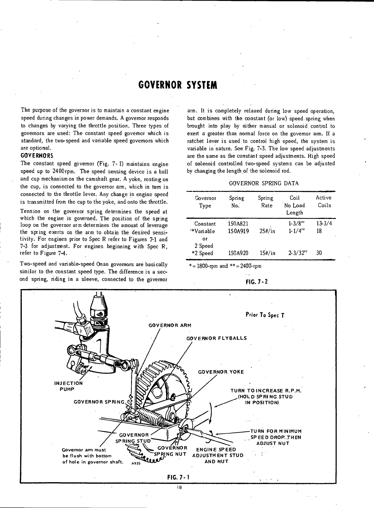
The
constant speed governor (Fig. 7-1) maintains engine
speed up to 2400rpm. The speed sensing device is a
ball
and
cup
mechanism
on
the camshaft
gear.
A
yoke,
resting
on
the cup, is connected to the governor arm,
which
in tum is
connected to the throttle lever.
Any
change in engine speed
is
transmitted
from
the cup to the
yoke,
and onto the
throttle.
Tension
on the governor spring determines the speed at
which
the engine is governed. The
position
of the spring
loop
on the governor arm determines the amount of leverage
the spring exerts on the arm to obtain the desired sensi-
tivity.
For engines
prior
to
Spec
R refer to Figures 7-1 and
7-3 for adjustment. For engines beginning
with
Spec
R,
refer
to Figure 7-4.
Two-speed
and variable-speed Onan governors are basically
similar
to the constant speed type. The
difference
is a
sec-
ond
spring,
riding
in a sleeve, connected to the governor
arm.
It is completely relaxed
during
low speed operation,
but
combines
with
the constant (or low) speed.spring when
brought
into
play by either manual or solenoid
control
to
exert a greater than normal force on the governor arm. If a
ratchet lever is used to
control
high
speed,
the system is
variable
in nature. See
Fig.
7-3. The
low
speed adjustments
are the
same
as the constant speed adjustments.
High
speed
of
solenoid
controlled
two-speed systems can be adjusted
by
changing
the
length
of the solenoid rod.
GOVERNOR
SPRING
DATA
Governor
Type
Spring
No.
Spring
Rate
Coil
No
Load
Length
Active
Coils
Constant
'•Variable
or
2
Speed
*2
Speed
150A821
150A919
25#/in
1-3/8"
1-1/4"
13-3/4
18
Constant
'•Variable
or
2
Speed
*2
Speed
150A920
15#/in
2-3/32"
30
*=
1800-rpm
and
**
=
2400
:
rpm
FIG.
7-2
INJECTION
PUMP
GOVERNOR
ARM
GOVERNOR FLYBALLS
GOVERNOR YOKE
Prior
To
Spec
T
TURN
TO
INCREASE R.P.M.
..(HOLD SPRI
NG
STUD
IN POSITION)
TURN
FOR
MINIMUM
SPEED DROP. THEN
ADJUST
NUT
Governor
arm
must
be flush with bottom
of hole
in
governor shaft.
ENGINE SPEED
ADJUSTMENT STUD
AND
NUT
FIG.
7-1
18
 Loading...


