FLYWHEEL
ALTERNATOR
There are
four
major components in the battery charging
system. (I) a permanent magnet on the
flywheel
provides a
rotating
magnetic
field;
(2) a group of coils mounted behind
the
flywheel
on the
gear
cover cut the
field
to produce a
voltage;
(31 a
2-step
mechanical regulator controls the ac
voltage
to the
rectifier,
and (4) a
full
wave
rectifier
con-
verts the regulated ac to dc
for
battery charging.
The permanent magnet
(rotor)
is held to the
flywheel
by
screws. It is
fully
supported by the
flywheel
and therefore
has no bearings. The stator windings are encapsulated in
an epoxy resin for protection
from
moisture.
Cooling
of
the stator is
from
special
fins
on the rotor. The
rectifier
is
located inside the blower housing and cooled by incoming
engine air. A fuse between the
rectifier
and ground pro-
tects the rectifiers
from
destruction should the battery be
connected in the
circuit with
reversed
polarity.
The mech-
anical
regulator cannot tolerate normal
vibration
of the
engine, so it must be mounted on a
separate
panel.
The alternator develops
two
different
rates
of current output.
The smaller output is connected in the charge
circuit
for a
continuous
low
rate charge. The larger output is controlled
by
the mechanical regulator,
which
has two relays, one of
which
is voltage sensitive. When battery voltage
falls
and
the voltage sensitive relay is de-energized, contacts close
to
provide a
circuit
to the other relay,
which
makes a
circuit
for
the
high
rate charge. See Fig. 10-2
wiring
schematic.
The voltage at
which
the sensitive relay is energized varies
with
the temperature.
The
final
result is a charge rate of 12-amperes
into
a 70-amp
hour,
12-volt
battery when the engine is
running
at 1,800-rpm.
The maximum continuous dc load is
limited
to 10-amperes
at 1,800-rpm. Reverse current through the
rectifiers
is 5 to
10-milliamperes,
so no special reverse current protection is
"needed. The engine should not be run
while
the battery is
disconnected, but if the battery is
accidentally
disconnected,
the system
will
not be damaged.
MAINTENANCE
There are neither
brushes
nor bearings in this system so
maintenance is
limited
to keeping the components in good
condition.
When the
flywheel
is off, clean the rotor and
stator and check the wires. In general, see that all connec-
tions
are
secure
and all components clean. If the alternator
is
operating
satisfactorily,
do not tamper
with
it.
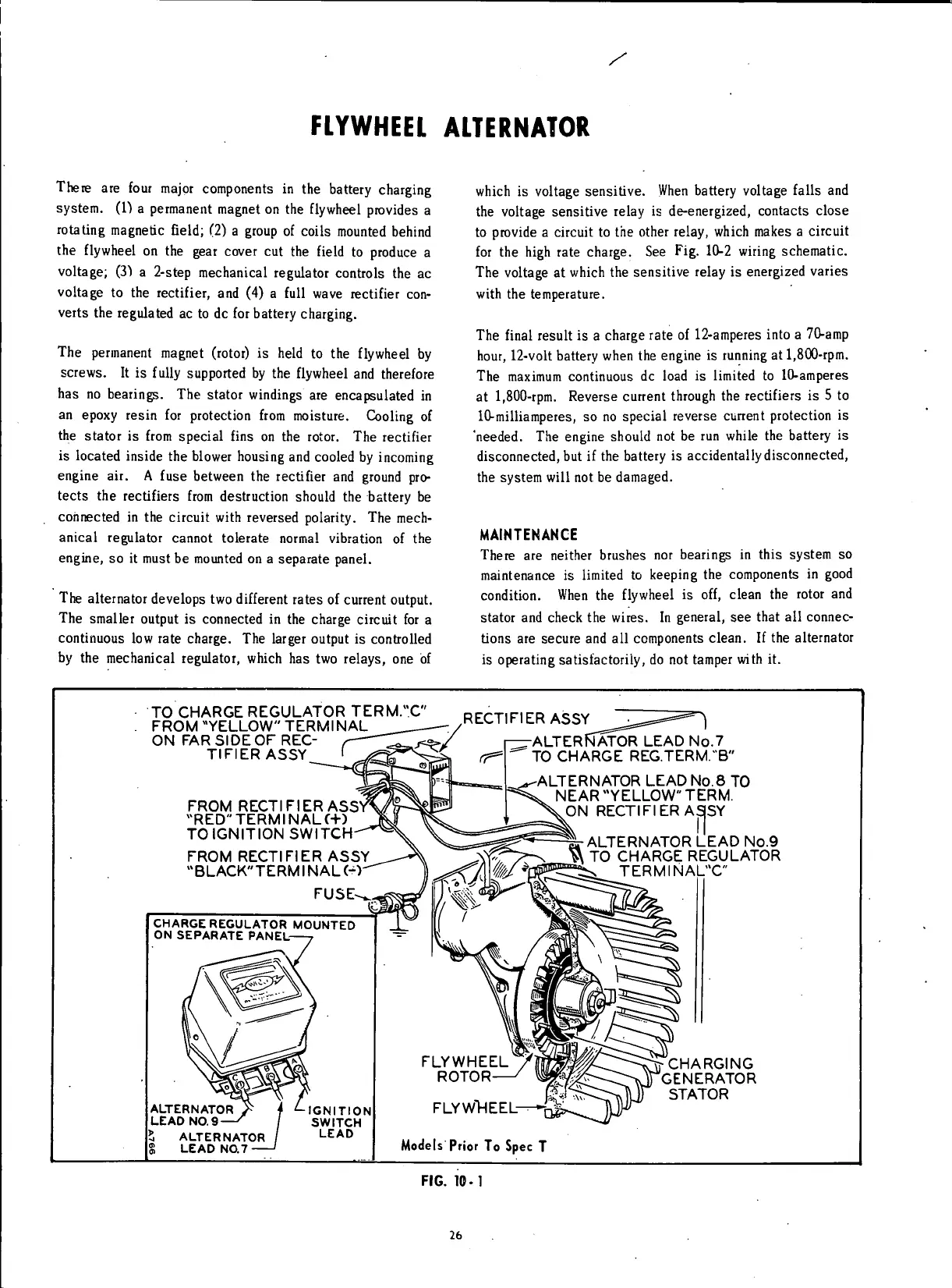
TO CHARGE REGULATOR TERM.X
FROM "YELLOW" TERMINAL
ON FAR SIDE OF REC-
TIFIER ASSY
FROM RECTIFIER ASSV
"RED"
TERM
I
NAL (+)
TO IGNITION SWITCH-
FROM RECTIFIER ASSY
"BLACK" TERMINALS)'
FUSE-
CHARGE REGULATOR MOUNTED
ON SEPARATE PANEL-
ALTERNATOR
LEAD
NO.9
5 ALTERNATOR
3 LEAD
NO.7
IGNITION
SWITCH
LEAD
RECTIFIER ASSY^J^^***"
1
>/ r^rALTERfWOR LEAD
No.7
-
— "
TO CHARGE REG.TERM. 'B"
-ALTERNATOR LEAD No.8
TO
NEAR "YELLOW" TERM.
ON RECTIFIER AS|SY
CM-
ALTERNATOR LEAD
No.9
^
TO
CHARGE REGULATOR
TERMINA
FLYWHEEL
ROTOR-
FLYWHEEL-
CHARGING
GENERATOR
STATOR
Models Prior
To
Spec
T
FIG.
10-1
26
 Loading...


