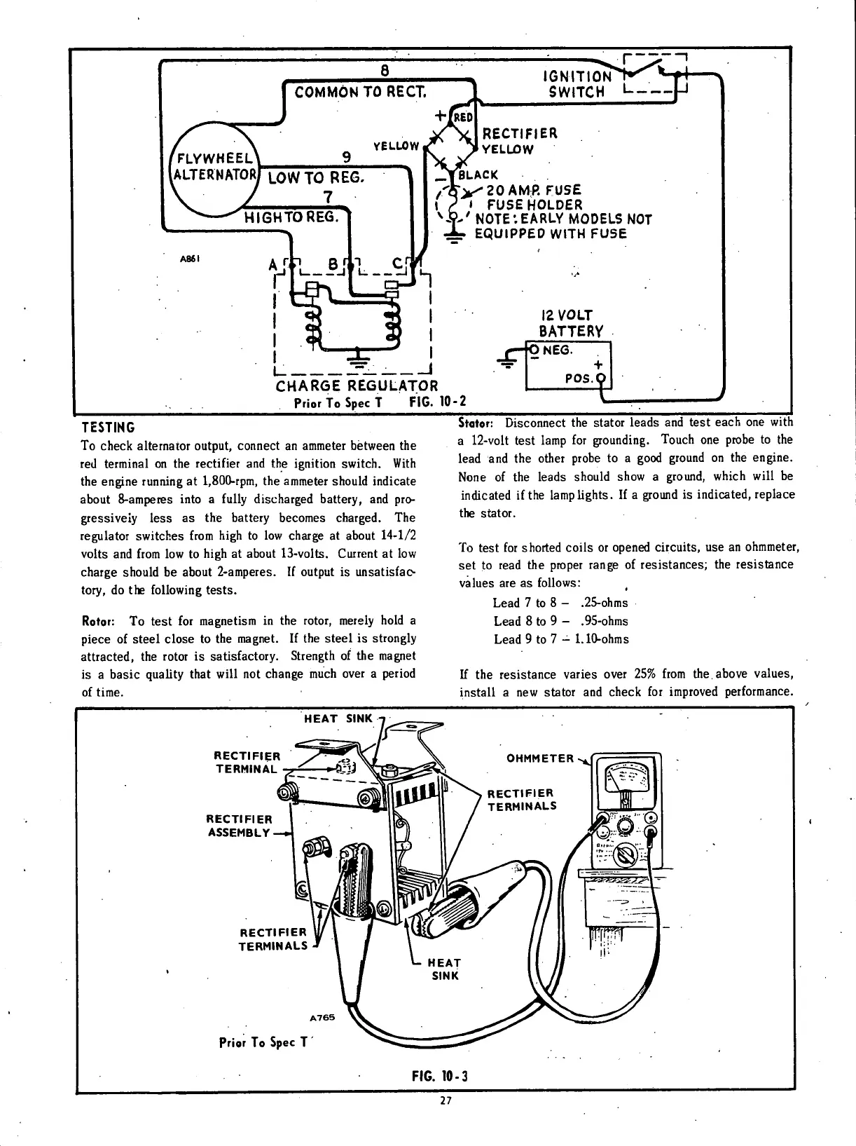
IGNITION
SWITCH
L
RECTIFIER
YELLOW
BLACK
20
AMP.
FUSE
I
FUSE
HOLDER
'
NOTE*.EARLY
MODELS
NOT
EQUIPPED
WITH
FUSE
12
VOLT
BATTERY
CHARGE
REGULATOR
Prior
To
Spec
T
FIG.
10-2
1
NEG.
POS.
T
\
TESTING
To
check alternator
output,
connect an ammeter between the
red
terminal
on the
rectifier
and the
ignition
switch.
With
the engine
running
at 1,800-rpm, the ammeter should indicate
about
8-amperes
into
a
fully
discharged battery, and
pro-
gressively
less
as the battery becomes charged. The
regulator
switches
from
high
to low charge at about 14-1/2
volts
and
from
low to
high
at about
13-volts.
Current at low
charge should be about 2-amperes. If output is unsatisfac-
tory,
do the
following
tests.
Rotor:
To test for magnetism in the
rotor,
merely
hold
a
piece of steel close to the magnet. If the steel is strongly
attracted,
the
rotor
is satisfactory. Strength of the magnet
is
a basic
quality
that
will
not change much over a
period
of
time.
Stator: Disconnect the stator leads and test each one
with
a
12-volt
test lamp for grounding.
Touch
one probe to the
lead
and the other probe to a good ground on the engine.
None
of the leads should show a ground,
which
will
be
indicated
ifthe
lamplights.
If a ground is
indicated,
replace
the stator.
To
test
for
shorted
coils
or opened
circuits,
use an ohmmeter,
set to read the proper range of resistances; the resistance
values are as
follows:
(
Lead
7 to 8 - .25-ohms
Lead
8 to 9 - .95-ohms
Lead
9 to 7 - 1.10-ohms
If
the resistance varies over 25%
from
the.
above
values,
install
a new stator and check for
improved
performance.
HEAT
SINK
RECTIFIER
TERMINAL
RECTIFIER
ASSEMBLY-
RECTIFIER
TERMINALS
Prior
To
Spec
T
FIG.
10-3
27
 Loading...


