ENGINE
DISASSEMBLY
CYLINDER
HEAD,
VAIVES
The
cylinder
head assembly has
alloy
hardened faced valves,
release
type rotators,
alloy
hardened inserts, guides, rocker
arms,
injection
nozzle and
glow
plug.
The push rods run
through
shields.
MAINTENANCE
Check the valve
clearances
at regular intervals. In
addition,
dean the combustion chamber 'and valve
seats
at regular
intervals.
VALVE
CLEARANCE
Check valve clearance when the engine is at
room
temper-
ature (about 70
o
n.
1.
Tum the
flywheel
until
the
cylinder
is on its compres-
sion
stroke. Use a socket wrench on the
flywheel
screw
hex head.
To
determine
ifthe
cylinder
is in its compression stroke,
observe the action of the push rods as the engine is
rotated
in a clockwise
direction.
The exhaust valve
push rod
will
be in its lowest
position
and the intake
valve
push rod
will
be
moving
downward. As the piston
reaches
top dead center, the
flywheel
timing
mark should
be aligned
with
the
timing
pointer and the valve push
rods stationary.
2.
Now
turn
the
flywheel
clockwise for an additional 10
to
45-degrees.
There is no
timing
mark for this
position
so it must be estimated.
With
the piston located in this
position,
it
will
be in its power stroke
with
both valves
completely
closed.
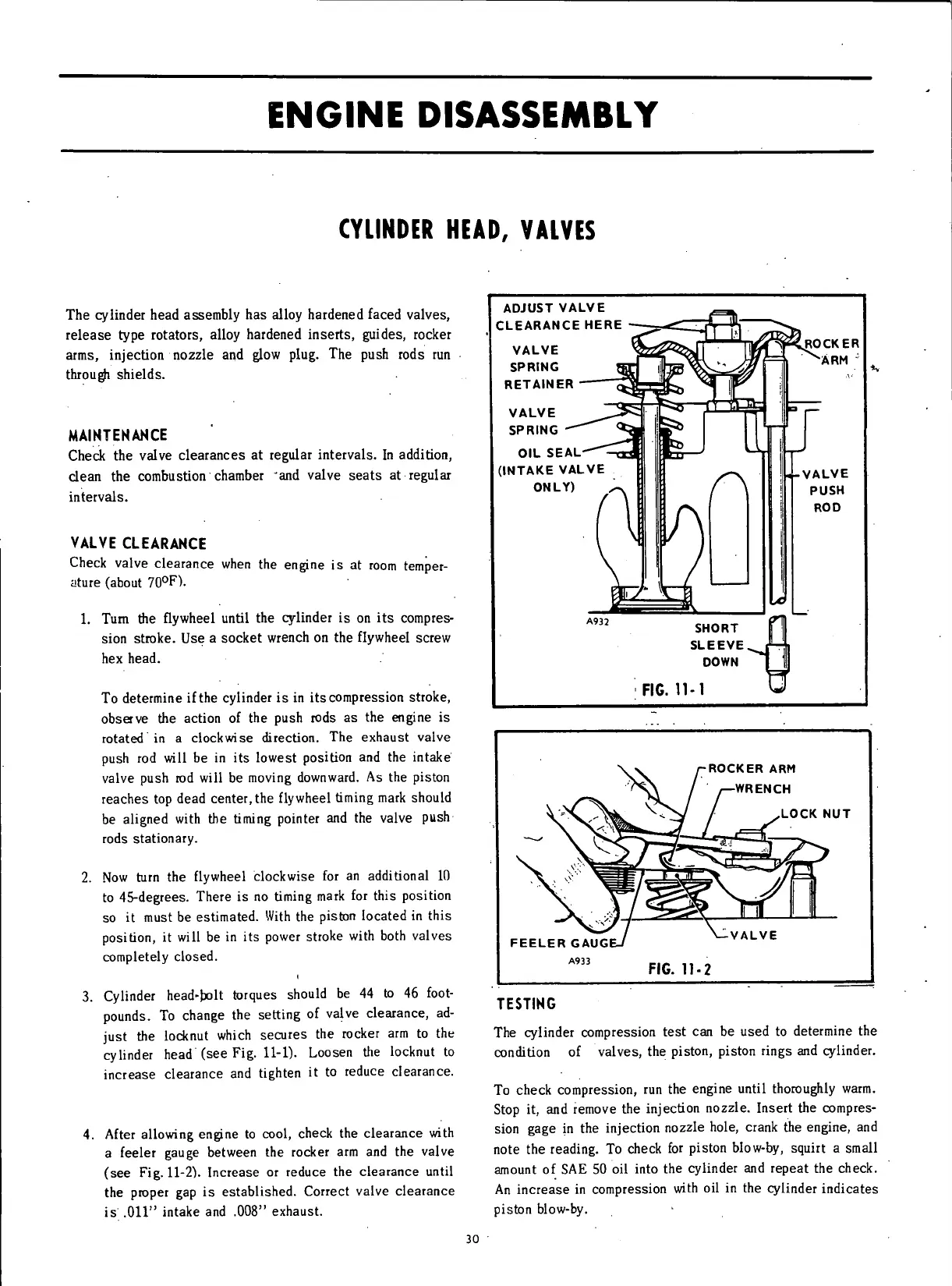
3.
Cylinder
head-bolt torques should be 44 to 46
foot-
pounds. To
change
the setting of valve clearance, ad-
just
the
locknut
which
secures
the rocker arm to the
cylinder
head (see Fig. 11-1). Loosen the
locknut
to
increase clearance and tighten it to reduce clearance.
4.
After
allowing
engine to
cool,
check the clearance
with
a feeler
gauge
between the rocker arm and the valve
(see
Fig.
11-2).
Increase or reduce the clearance
until
the proper gap is established. Correct valve clearance
is
.011" intake and .008" exhaust.
ADJUST
VALVE
CLEARANCE
HERE
VALVE
SPRING
RETAINER
VALVE
SPRING
OIL
SEAL-
(INTAKE
VALVE
ONLY)
f
LROCKER
"ARM
;
FIG.
11-1
ROCKER
ARM
WRENCH
LOCK
NUT
FEELER
GAUG
A933
VALVE
FIG.
11-2
TESTING
The
cylinder
compression test can be used to determine the
condition
of valves, the piston, piston rings and cylinder.
To
check compression, run the engine
until
thoroughly
warm.
Stop it, and remove the
injection
nozzle. Insert the compres-
sion
gage
in the
injection
nozzle hole, crank the engine, and
note the reading. To check for piston
blow-by,
squirt a small
amount of SAE 50 oil
into
the
cylinder
and
repeat
the check.
An
increase in compression
with
oil in the
cylinder
indicates
piston
blow-by.
30
 Loading...


