COOLING
SYSTEM
To
remove
heat
produced during operation,
engines
use
a
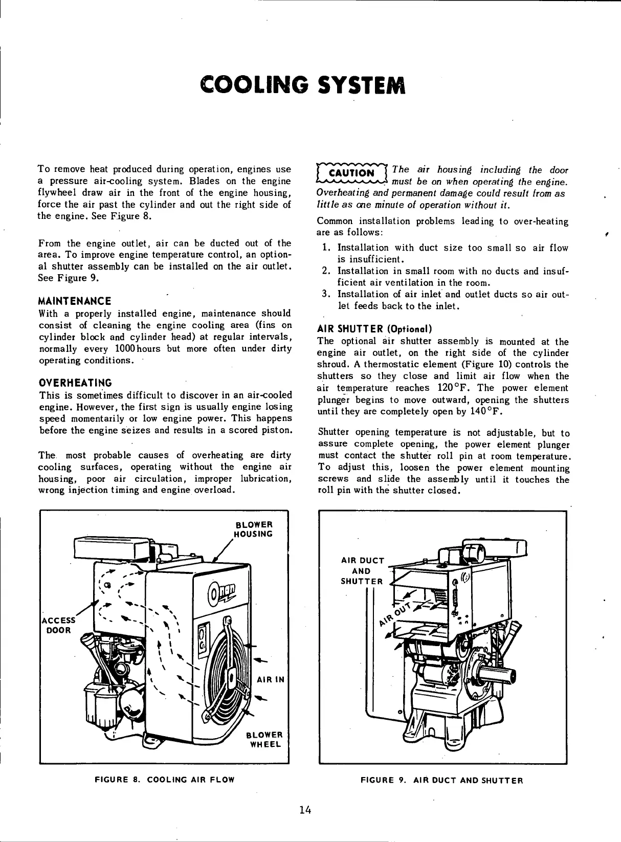
pressure
air-cooling system. Blades on the engine
flywheel
draw air in the
front
of the engine housing,
force
the air
past
the cylinder and out the
right
side of
the engine. See Figure 8.
From
the engine outlet, air can be ducted out of the
area.
To improve engine temperature control, an option-
al
shutter assembly can be installed on the air outlet.
See Figure 9.
MAINTENANCE
With
a properly installed engine, maintenance should
consist of cleaning the engine cooling
area
(fins
on
cylinder
block and cylinder
head)
at regular intervals,
normally
every
1000
hours but more often under
dirty
operating conditions.
OVERHEATING
This
is sometimes
difficult
to discover in an air-cooled
engine. However, the
first
sign is usually engine losing
speed
momentarily or low engine power. This
happens
before the engine
seizes
and results in a scored piston.
The most probable
causes
of overheating are
dirty
cooling
surfaces, operating
without
the engine air
housing, poor air circulation, improper lubrication,
wrong
injection
timing
and engine overload.
The
air
housing including
the
door
must
be on
when operating
the
engine.
Overheating
and
permanent damage could result from
as
little
as one
minute
of
operation without
it.
Common
installation problems leading to over-heating
are as
follows:
1.
Installation
with
duct size too small so air
flow
is
insufficient.
2.
Installation in small room
with
no ducts and insuf-
ficient
air
ventilation
in the room.
3. Installation of air
inlet
and outlet ducts so air out-
let
feeds
back to the
inlet.
AIR
SHUTTER
(Optional)
The optional air shutter assembly is mounted at the
engine air outlet, on the
right
side of the cylinder
shroud. A thermostatic element (Figure 10) controls the
shutters so they close and
limit
air
flow
when the
air
temperature
reaches
120
0
F. The power element
plunger begins to move outward, opening the shutters
until
they are completely open by 140
0
F.
Shutter opening temperature is not adjustable, but to
assure
complete opening, the power element plunger
must contact the shutter
roll
pin at room temperature.
To
adjust this, loosen the power element mounting
screws and slide the assembly
until
it
touches
the
roll
pin
with
the shutter closed.
BLOWER
HOUSING
ACCESS
DOOR
AIR
IN
BLOWER
WHEEL
AIR
DUCT
AND
SHUTTER
FIGURE
8.
COOLING
AIR
FLOW
FIGURE
9. AIR
DUCT
AND
SHUTTER
14
 Loading...


