INSTALLATION
GENERAL
Plan the installation carefully to insure maximum oper-
ating
efficiency. Use this manual as a general guide.
Recommendations in this manual are
based
on extensive
tests
under favorable operating conditions. Abide by
pertinent local
codes
regulating installation and opera-
tion
of internal combustion engines.
LOCATION
Engine location is determined
chiefly
by the intended
application.
Provide
adequate
access
for service and
repair. Protect the engine
from
adverse
weather. Con-
sider the location of related
systems,
such as
fuel,
exhaust,
and ventilation.
MOUNTING
Secure
the engine to a
rigid,
level foundation. Founda-
tions must be sturdy enough to withstand distortion and
retain
alignment
with
complementary equipment.
If
necessary
to exceed
23-degree
tilt
angle, consult
the factory.
Compensate
for any
tilt
when checking
crankcase
oil.
VENTILATION
Ventilation
is
needed
to cool the engine and support
combustion.
Avoid
recirculation of ventilating air. See
Specifications Section for air
flow
requirements and
vent
sizes.
Locate vents so air
flow
from
the inlet to the outlet
will
pass
over the.engine. The outlet should be
slightly
higher than the inlet.
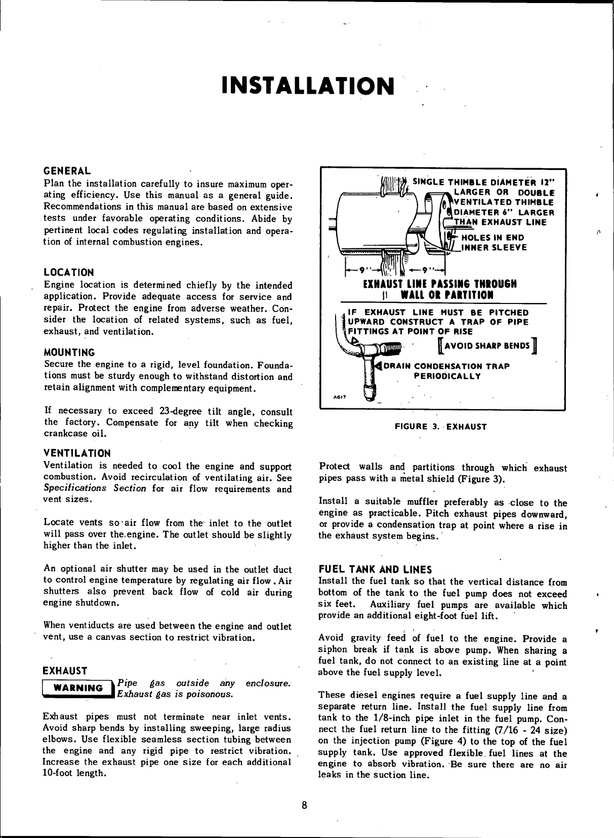
SINGLE
THIMBLE
DIAMETER
12"
LARGER
OR
DOUBLE
'•^VENTILATED
THIMBLE
DIAMETER
6
,
•
LARGER
THAN
EXHAUST
LINE
HOLES
IN END
INNER
SLEEVE
EXHAUST
LINE
PASSING
THROUGH
|l WAU
01
PAIT
IT ION
IF
EXHAUST
LINE
MUST
BE
PITCHED
UPWARD
CONSTRUCT
A
TRAP
OF
PIPE
FITTINGS
AT
POINT
OF
RISE
AVOID
SHARP
BENDS
I UP
[DRAIN
CONDENSATION
TRAP
PERIODICALLY
FIGURE
3.
EXHAUST
Protect walls and partitions through
which
exhaust
pipes
pass
with
a metal shield (Figure 3).
Install
a suitable
muffler
preferably as close to the
engine as practicable. Pitch
exhaust
pipes downward,
or provide a condensation trap at point where a rise in
the
exhaust
system begins.
An
optional air shutter may be
used
in the outlet duct
to
control engine temperature by regulating air
flow
.
Air
shutters
also
prevent back
flow
of
cold
air during
engine shutdown.
When
ventiducts are
used
between the engine and outlet
vent, use a
canvas
section to restrict vibration.
EXHAUST
WARNING
I
Pipe
gas
outside
any
Exhaust
gas is
poisonous.
enclosure.
Exhaust pipes must not terminate
near
inlet vents.
Avoid
sharp
bends
by installing sweeping, large radius
elbows. Use
flexible
seamless
section tubing between
the engine and any
rigid
pipe to restrict vibration.
Increase
the
exhaust
pipe one
size
for
each
additional
10-foot
length.
FUEL
TANK
AND
LINES
Install
the
fuel
tank so that the vertical distance
from
bottom
of the tank to the
fuel
pump
does
not exceed
six
feet.
Auxiliary
fuel
pumps are available
which
provide
an additional eight-foot
fuel
lift.
Avoid
gravity feed of
fuel
to the engine. Provide a
siphon break if tank is
above
pump. When sharing a
fuel
tank, do not connect to an existing line at a point
above
the
fuel
supply
level.
These
diesel
engines
require a
fuel
supply line and a
separate
return
line.
Install the
fuel
supply line
from
tank to the 1/8-inch pipe inlet in the
fuel
pump. Con-
nect the
fuel
return line to the
fitting
(7/16 - 24 size)
on
the injection pump (Figure 4) to the top of the
fuel
supply tank. Use approved
flexible,
fuel
lines at the
engine to
absorb
vibration. Be
sure
there
are no air
leaks
in the suction
line.
 Loading...


