Repair
If cleaning will not eliminate a nozzle defect, replace
the nozzle or take it to an authorized service station.
Do not attempt to replace nozzle parts except for the
nozzle and pintle assembly.
Assembly
Rinse both the valve and nozzle thoroughly before
assembly and coat with oil. The valve must be free in
the nozzle. Lift it about. 1/3 way out of the body. It
should slide back to its seat without aid when the
assembly is held at a 45-degree angle. If necessary,
work the valve into its body with clean mutton tallow.
1.
Remove all pressure on the nozzle spring by
adjusting the pressure adjusting screw.
2..
Clamp the nozzle holder body in a vise.
3. Set the val ve in the body and set the nozzle over it.
4.
Install the nozzle cap nut loosely.
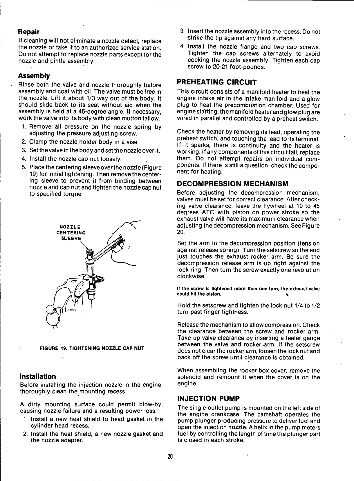
5. Place the centering sleeveoverthe nozzle (Figure
19)
for initial tightening. Then remove the center-
ing sleeve to prevent it from binding between
nozzle and cap nut and tighten the nozzle cap nut
to specified torque.
NOZZLE
CENTERING
SLEEVE
FIGURE 19. TIGHTENING NOZZLE CAP NUT
3. Insert the nozzle assembly into the recess. Do not
strike the tip against anytiard surface.
4.
Install the nozzle flange and two cap screws.
Tighten the cap screws alternately to avoid
cocking the nozzle assembly. Tighten each cap
screw to 20-21 foot-pounds.
PREHEATING
CIRCUIT
This circuit consists of a manifold heater to heat the
engine intake air in the intake manifold and a glow
plug to heat the precombustion chamber. Used for
engine starting, the manifold heater and glow plug are
wired in parallel and controlled by a preheat switch.
Check the heater by removing its
lead,
operating the
preheat switch, and touching the lead to its terminal.
If it sparks, there is continuity and the heater is
working.
If any components of this circuitfail, replace
them.
Do not attempt repairs on individual com-
ponents. If there is still a question, check the compo-
nent for heating.
DECOMPRESSION
MECHANISM
Before adjusting the decompression mechanism,
valves must be set for correct clearance. After check-
ing valve clearance, leave the flywheel at 10 to 45
degrees ATC with piston on power stroke so the
exhaust valve will have its maximum clearance when
adjusting the decompression mechanism. See Figure
20.
Set the arm in the decompression position (tension
against release spring). Turn the setscrew so the end
just touches the exhaust rocker arm. Be sure the
decompression release arm is up right against the
lock
ring.
Then turn the screw exactly one revolution
clockwise.
If the screw is tightened more than one tum, the exhaust valve
could hit the piston. %
Hold the setscrew and tighten the lock nut 1/4 to 1/2
turn past finger tightness.
Release the mechanism to allow compression. Check
the clearance between the screw and rocker arm.
Take up valve clearance by inserting a feeler gauge
between the valve and rocker arm. If the setscrew
does not clear the rocker arm, loosen the lock nut and
back off the screw until clearance is obtained.
Installation
Before installing the injection nozzle in the engine,
thoroughly clean the mounting recess.
A dirty mounting surface could permit blow-by,
causing nozzle failure and a resulting power loss.
1.
Install a new heat shield to head gasket in the
cylinder head recess.
2.
Install the heat shield, a new nozzle gasket and
the nozzle adapter.
When assembling the rocker box cover, remove the
solenoid and remount it when the cover is on the
engine.
INJECTION
PUMP
The single outlet pump is mounted on the left side of
the engine crankcase. The camshaft operates the
pump plunger producing pressure to deliver fuel and
open the injection nozzle. A helix in the pump meters
fuel by controlling the length of time the plunger part
is closed in each stroke.
20
 Loading...


