11451 Belcher Road South, Largo, FL 33773 • USA • Tel +1 (727) 447-6140 • Fax +1 (727) 442-5699 • sales@onicon.com
F-3500 Insertion Electromagnetic Flow Meter Manual 02/18 - 0665-11 Page 16
Tools needed for standard installation:
• 1
5
/
16
” wrench or adjustable wrench
•
5
/
8
” wrench or small adjustable wrench
• Pipe wrench (to hold valve in place)
• Pipe thread sealant
CAUTION
If there are any leaks around the clamping nut or stem, DO NOT ATTEMPT TO STOP THE
LEAKAGE BY OVERTIGHTENING THE CLAMPING NUT. Damage to this nut or the clamping
ring under the nut may prevent the assembly from properly holding the meter in the pipe. The
clamping nut is not part of the sealing mechanism. Any leaks in this area indicate that the
“O” ring is not sealing properly and you must contact ONICON for assistance.
WARNING
When you are ready to rell the system, make sure that all lines are lled with water before
inserting the meter into the ow stream. If the lines are not lled and this is a hot water
system, some water may ash to steam and exceed the high temperature limit for the sensor
head assembly. This ash over could also exceed the pressure ratings of the meter and the
assembly could fail allowing steam and hot water to escape causing serious injury.
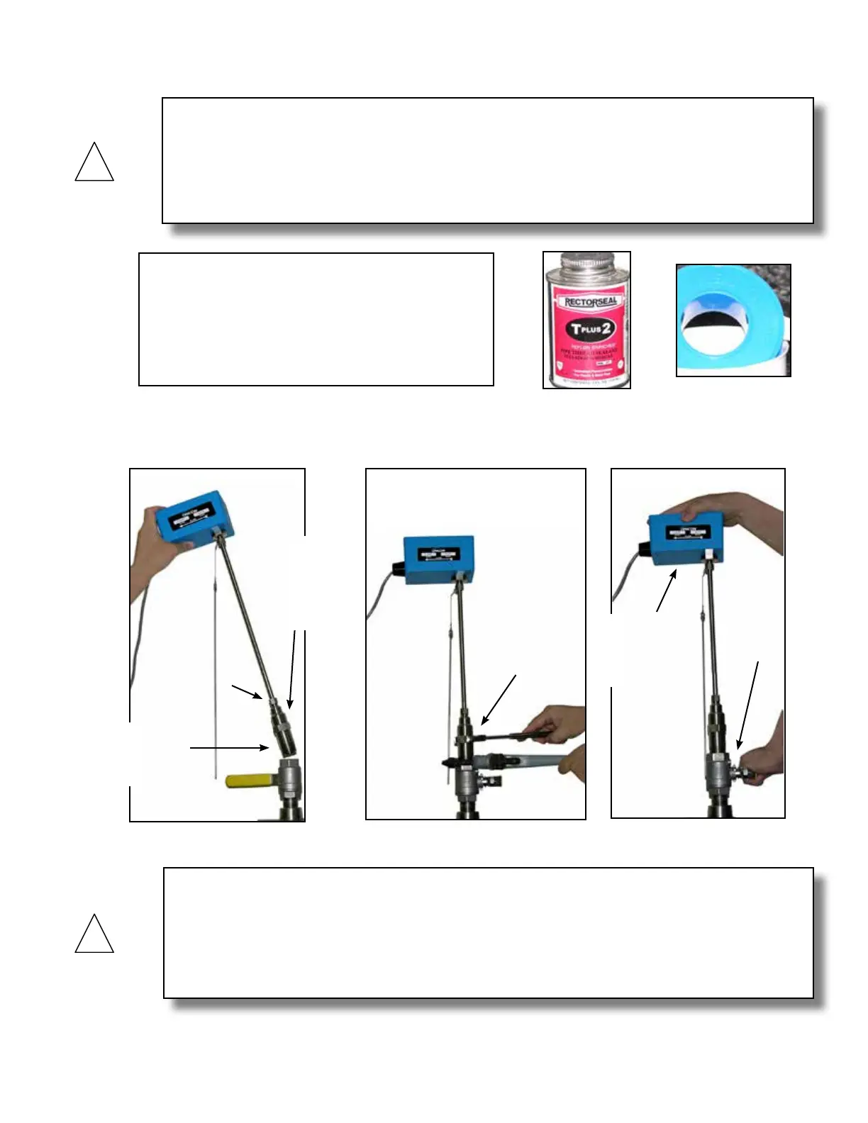
3.2.7 Installing the Flow Meter
Flush, ll and pressure test the piping system prior to installing the meter. Loosen clamping
nut to facilitate installation.
Clamping nut
Keep sensor
head fully
withdrawn
during
installation.
Apply paste or
Teon tape as
necessary.
Thread hot
tap adapter on
to ball valve
and tighten as
necessary.
Maintain a rm
grip on the
enclosure when
opening valve.
Crack
valve to
test for
leaks.