11451 Belcher Road South, Largo, FL 33773 • USA • Tel +1 (727) 447-6140 • Fax +1 (727) 442-5699 • sales@onicon.com
F-3500 Insertion Electromagnetic Flow Meter Manual 02/18 - 0665-11 Page 17
Begin by calculating the effort that will be required to hold the meter. Establish adequate footing
for this task, taking extra caution when working from a ladder or platform. Use the following
formula:
E=0.11 x P Where: E = effort in pounds
P = system pressure in pounds per square inch
Example: In a 300 PSI system, 33 pounds of effort is required to insert the meter into the pipe.
3.3.1 Inserting Standard Conguration Flow Meters
WARNING
SYSTEM MAY BE UNDER HIGH PRESSURE. When adjusting the meter position or removing
it, be sure to hold the electronics enclosure rmly by hand before SLOWLY loosening the
positioning clamping nut. Failure to do this will allow the pressure to suddenly and rapidly
force the meter from the pipe causing serious injury. The meter could also be damaged or break
apart causing a break in the water seal with the resultant loss of large amounts of water. The
hand effort required to hold the meter will be 0.11 times the pipe pressure.
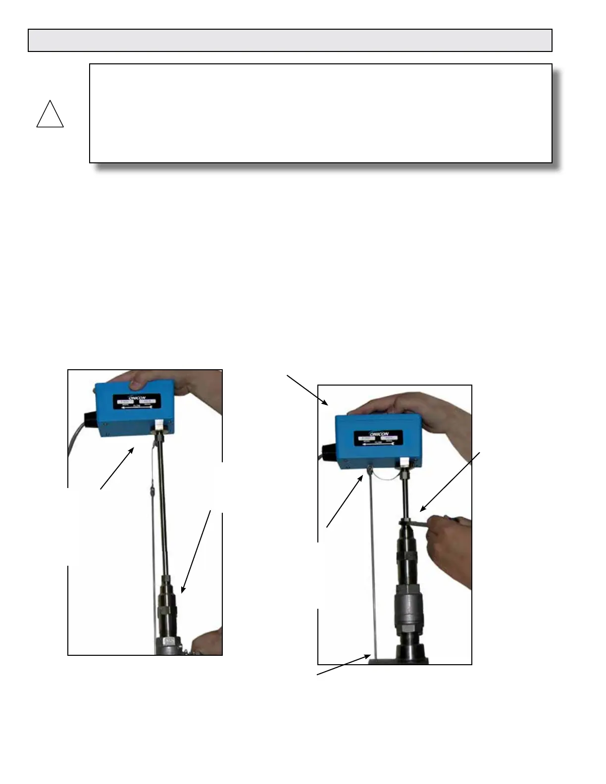
Step 2:
Slowly open the
valve to the full
open position.
Step 1:
Maintain a rm grip
on the enclosure
to counteract
the eects of the
pressure in the pipe.
Step 4:
Orient the enclosure to parallel with the pipe and
in alignment with the ow direction arrow.
Step 3:
Use the end of the depth gage to pierce any
insulation that may be present and rest the
gage on the outside wall of the pipe.
Step 6:
Carefully tighten
the clamping
nut. DO NOT
OVERTIGHTEN.
Step 5:
Slowly push down on
the ow meter until
the bottom of the
enclosure rests on the
top of the depth gage.
3.3 INSERTION OF THE METER

 Loading...


