11451 Belcher Road South, Largo, FL 33773 • USA • Tel +1 (727) 447-6140 • Fax +1 (727) 442-5699 • sales@onicon.com
F-3500 Insertion Electromagnetic Flow Meter Manual 02/18 - 0665-11 Page 11
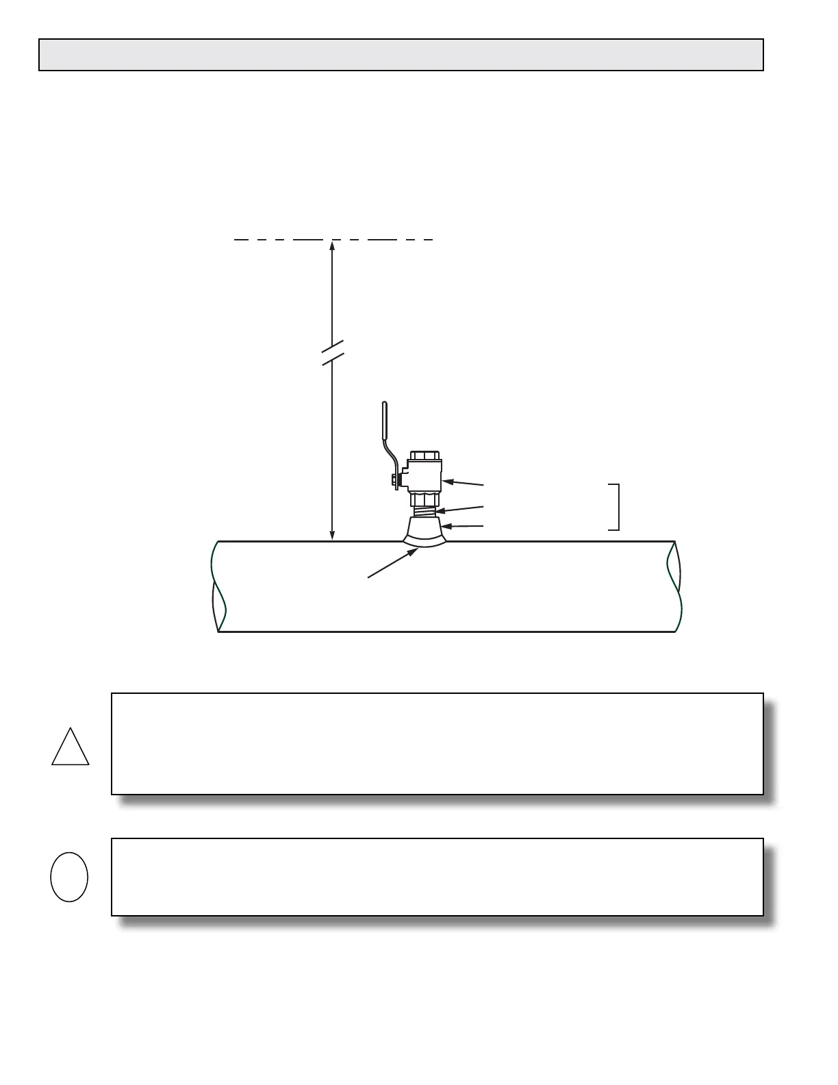
3.2 MECHANICAL INSTALLATION
ONICON Insertion Electromagnetic Flow Meters employ a hot tap adapter design that allows for
insertion and removal, when necessary, without interrupting ow and draining the pipe. To take
advantage of this feature, the ow meter must be installed through an isolation valve. The
installation must allow for sufcient overhead clearance to fully extract the meter, and a full 1”
opening in the pipe wall is required to clear the sensor head and allow for insertion. Make sure
that your valves and ttings are full port and at least 1” in actual internal diameter.
CAUTION
ONICON insertion style ow meters must be installed through a valve assembly. Failure to do
so negates the ability to remove the meter without shutting down and draining the system. It
will also result in an excessive amount of stem protruding from the pipe. Excessive stem lengths
unnecessarily expose the meter to incidental damage.
IMPORTANT NOTE
Flow meters installed through oversized access holes will be subjected to undesirable turbulence
that may affect the accuracy of the meter.
Typically
30 - 40"
depending on
pipe size and
height of valve
assembly.
CLEARANCE
REQUIRED
FOR INSTALLATION
Minimum Hole Size = 1"
Must be centered
Standard Installation
Kit for Steel Pipe
1" Full port ball valve
1" Close nipple
1" Branch outlet
1¼" for
hot tap
NOTE: Use stainless steel or brass
close nipple only.