11451 Belcher Road South, Largo, FL 33773 • USA • Tel +1 (727) 447-6140 • Fax +1 (727) 442-5699 • sales@onicon.com
F-3500 Insertion Electromagnetic Flow Meter Manual 02/18 - 0665-11 Page 10
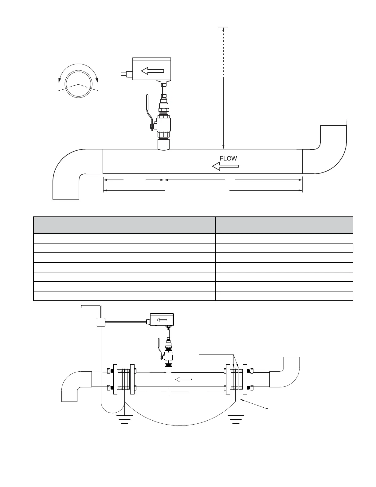
Typical Installation In Non-conductive Pipe
5 DIA
10 DIA
Gaskets (4 pl)
Grounding Rings (2pl)
Upstream obstruction
(A) Minimum straight run required
upstream of meter location
Single bend preceded by ≥ 9 diameters of straight pipe 10 Diameters
Pipe size reduction / expansion in straight pipe run 10 Diameters
Single bend preceded by ≤ 9 diameters of straight pipe 15 Diameters
Outowing tee / Pump outow 20 Diameters
Multiple bends out of plane 30 Diameters
Inowing tee 30 Diameters
Control / Modulating valve 30 Diameters
For 3” and larger pipe diameters
5 Dia.
A
• Acceptable to install in vertical pipe
• Position meter anywhere in upper 240°
for horizontal pipe
Available Straight Run*
CLEARANCE
REQUIRED
FOR INSTALLATION
30 - 40”
Depending on
pipe size
Installation with Grounding Rings
with Non-conductive Pipe
* Additional straight run may be required upstream of the upstream grounding ring based on the nature of
the upstream obstruction. Refer to the chart above to determine how much straight run is required.
*
 Loading...


