11451 Belcher Road South, Largo, FL 33773 • USA • Tel +1 (727) 447-6140 • Fax +1 (727) 442-5699 • sales@onicon.com
F-3500 Insertion Electromagnetic Flow Meter Manual 02/18 - 0665-11 Page 5
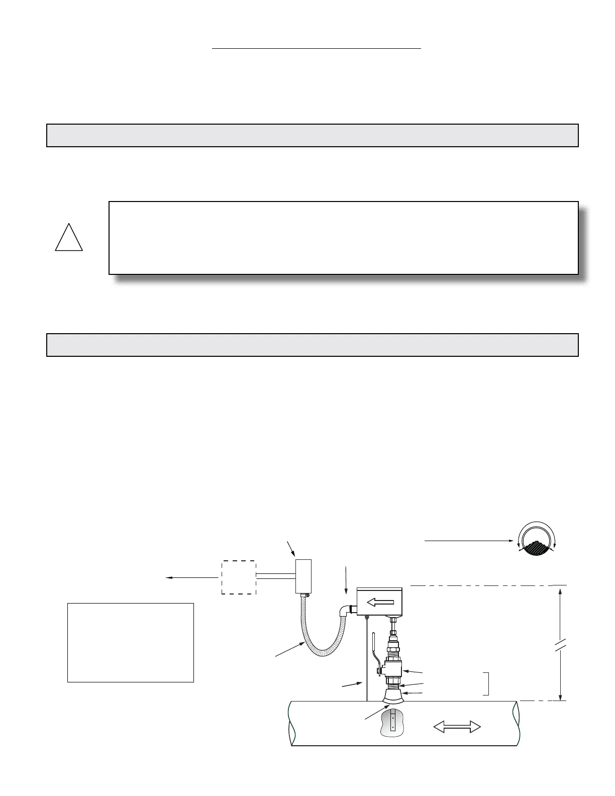
Typical Meter Installation
(New construction or scheduled shutdown)
½" FNPT
conduit connection
Insertion depth
gage provided
with each meter
FLOW
Customer provided
conduit and adapters
Output signal(s)
to control
system
ONICON
Display or
BTU Meter
(Optional)
Allow enough slack
in the flexible conduit
to permit the meter
to be removed
from the valve.
Typically
30 - 40"
depending on
pipe size and
height of valve
assembly.
CLEARANCE
REQUIRED
FOR INSTALLATION
Standard Installation
Kit for Steel Pipe
1" Full port ball valve
1" Close nipple
1" Branch outlet
1¼" for
hot tap
Minimum Hole Size = 1"
Must be centered
Note: Installation kits vary based on pipe material and application. For installations in pressurized (live)
systems, use "Hot tap" 1¼ inch installation kit and drill hole using a 1 inch wet tap drill.
• Install in vertical or horizontal pipe
• For horizontal pipe position meter
anywhere in upper 240˚
Typical Meter Installation
(New Construction or Scheduled Shutdown)
This guide is the basic reference tool for all ONICON F-3500 Electromagnetic Flow Meters. If
you have not purchased all of the options, there will be references in this manual which are not
applicable to your meter(s).
1.2 TYPICAL INSERTION ELECTROMAGNETIC FLOW METER
Faraday’s Law of electromagnetic induction states that a voltage will be induced in a conductor
when it passes through a magnetic eld, and the induced voltage will be directly proportional to
the velocity of the conductor.
ONICON F-3500 Electromagnetic Flow Meters generate pulsating magnetic elds that are used
to induce a voltage into the conductive uid owing through the pipe. Electrodes located on the
ow meter sensor head measure the induced voltage. Circuitry within the ow meter electronics
enclosure then converts the voltage to digital and analog signals that convey ow rate and total
data via connecting the cable to any of ONICON’s display devices, Btu meters and/or to a data
acquisition system.
SECTION 1.0: INTRODUCTION
We, at ONICON Incorporated, would like to thank you for purchasing our quality American made
F-3500 Electromagnetic Flow Meter. As our valued customer, our commitment to you is to provide
fast reliable service, while continuing to offer you quality products to meet your growing ow
measurement needs.
1.1 PURPOSE OF THIS GUIDE
We have written this guide to provide the persons responsible for the installation, operation and
maintenance of your ow meter with the most specic equipment information they will need.
This is NOT an electrical or plumbing trade manual.
WARNING
Please do not permit persons to install, operate or maintain this equipment unless they have a
complete knowledge of their trade skills and are competent to work on high pressure hot and cold
water and steam systems, according to their individual trades. Death or permanent injury may
result from accidents with these systems.
Note: Installation kits vary based on
pipe material and application.
For installations in pressurized
(live) systems, use “Hot tap” 1¼”
installation kit and drill hole using a
1” wet tap drill.
*Small pipe conguration meters utilize
an insertion depth tool.
*