11451 Belcher Road South, Largo, FL 33773 • USA • Tel +1 (727) 447-6140 • Fax +1 (727) 442-5699 • sales@onicon.com
F-3500 Insertion Electromagnetic Flow Meter Manual 02/18 - 0665-11 Page 13
3.2.4 Customer Supplied Installation Hardware
There are occasions where circumstances require that the customer provide the
installation hardware or that the ow meter must be installed through existing hardware.
In these cases, it is important to conrm that the installation hardware is suitable for use
with the ow meter provided by ONICON before it is installed. The installation must
allow for sufcient overhead clearance to fully extract the meter and a full 1” opening in
the pipe wall is required to clear the sensor head and allow for insertion. Make sure that
your valves and ttings are full port and at least 1” in actual internal diameter.
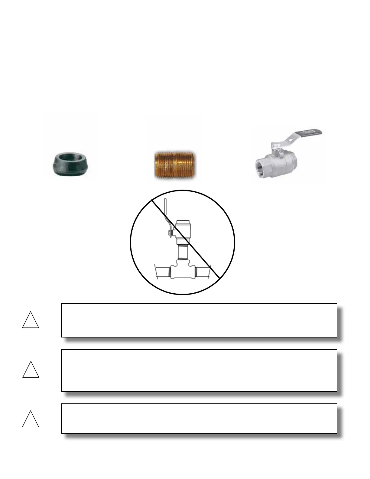
Installation hardware generally consists of three separate component parts:
CAUTION
In order to provide the ow meter with the correct stem length, ONICON must know the
overall height of the installation hardware as measured from the outside wall of the pipe to
the top of the valve where the meter is installed.
CAUTION
Use stainless steel or brass nipple only.
CAUTION
Do not use threaded steel or slip PVC tees to provide the 1” opening in the pipe. Tees of this
type will cause signicant errors in the ow measurement.
Some type of
threaded branch
outlet,
An
interconnecting
close nipple,
And a full port
isolation valve.