11451 Belcher Road South, Largo, FL 33773 • USA • Tel +1 (727) 447-6140 • Fax +1 (727) 442-5699 • sales@onicon.com
F-3500 Insertion Electromagnetic Flow Meter Manual 02/18 - 0665-11 Page 24
4.1 HELPFUL HINTS FOR START-UP AND COMMISSIONING
A step-by-step procedure and companion worksheet are located on the next two pages. Please
read all installation instructions carefully before proceeding with installation, start-up and
commissioning.
Please read these helpful hints before proceeding with the start-up and commissioning procedure
on the next page.
1. ONICON ow meters are individually calibrated for a particular application. Be sure to
verify the pipe size and location.
2. The electronic ow sensing systems will not work in air.
3. When measuring analog output signals, remember that current (mA) must be measured in
series, while voltage is measured in parallel. If the 4-20 mA signal is already connected to a
control system, you must break the connection and measure the signal in series.
4. When measuring frequency outputs in Hz, take your multimeter out of “auto-range mode”
and manually set the range for a voltage level above 15 VDC. This will prevent false readings
when signal is not present.
5. All wiring connections should be made at the end of the factory cable. Do not attempt to
remove the factory installed cable or change the orientation of the electronics enclosure.
6. Never connect power to analog or frequency output signal wires. ONICON F-3500
Flow meters are not “loop powered” devices.
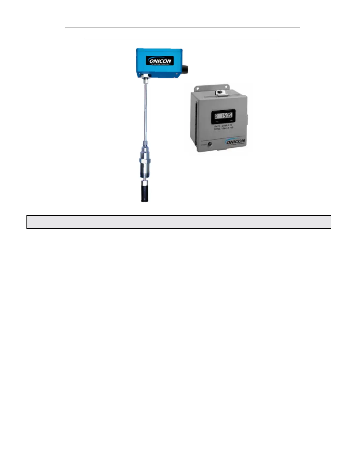
SECTION 4.0: START-UP & COMMISSIONING FOR ONICON
INSERTION ELECTROMAGNETIC FLOW METERS