FT
-
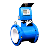
3500 ELECTROMAGNETIC FLOW METER
ONICON Incorporated 727.447.6140 Page 29 onicon.com
Earth wiring connections for use with grounding rings
3.6.1 Earth Connection
FT-3500 Electromagnetic Flow Meters are designed to detect microvolt signal levels at the electrodes located on the
sensor head. These signals are generated as conductive uids ow through the magnetic eld generated by the meter.
If enough random electrical noise is present at the electrodes, it can interfere with the ow measurement. Care must be
taken during installation to minimize the eects of electrical noise on the ow meter.
The most eective way to minimize the eects of electrical noise is to make sure that the pipe, the uid and the ow meter
body are all connected to earth ground. This accomplishes two important goals. First, it ensures that the pipe, uid and
ow meter are all at the same electrical potential, and second, it ensures that this electrical potential is the same as earth
ground.
In order to be certain that the meter is properly connected to earth, the ow meter earth cable should be run directly
to a known earth connection. The length of this earth cable should be as short as practically possible, preferably ≤25
feet in length. The table below lists earth connections from best to worst. If necessary, a separate earth cable should be
connected to the metal pipe near the meter.
IMPORTANT NOTE
Under certain circumstances, connecting the meter to earth through the green/yellow earth wire may increase
the amount of electrical noise present at the meter. Contact ONICON for technical assistance if you experience
increased noise levels with the earth wire connected to earth.
Earth Connections (stranded wire 14 – 18 AWG)
Best Earth grounding rod driven into the ground
Earth wire connected directly to the building electrical service panel.
Worst Earth wire connection inside an electrical outlet near the meter.
CAUTION
Failure to provide a proper earth connection to the meter may result in excessive electrical noise that will interfere
with the operation of the meter.
3.6 Signal and Power Wiring Connections