FT
-
3500 ELECTROMAGNETIC FLOW METER
ONICON Incorporated 727.447.6140 Page 49 onicon.com
5.4 NETWORK CONFIGURATION
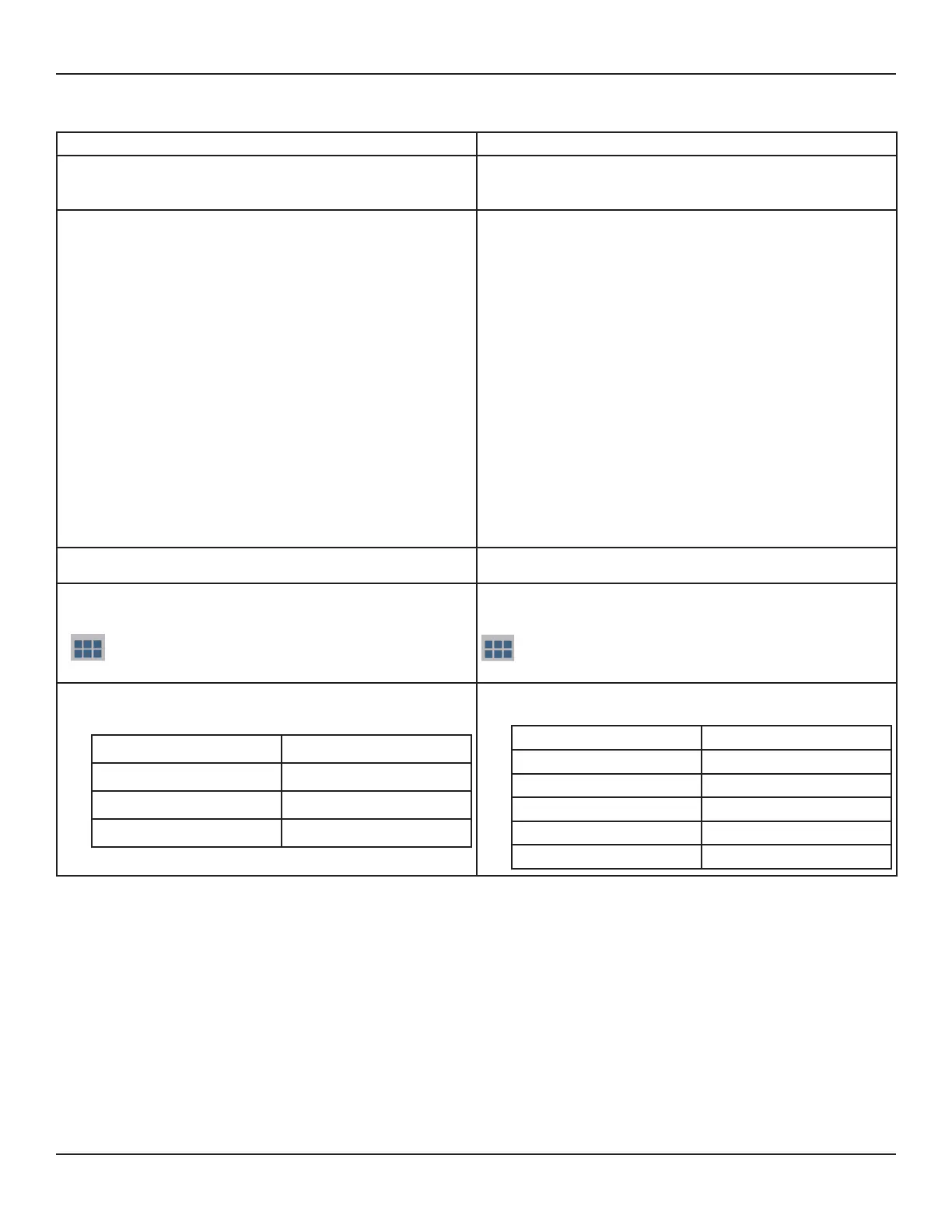
Checking Network Status
Connecting via RS-485 Connecting via IP
1. Power on unit to verify is it functioning properly. Once
veried, power unit down.
1. Power on unit to verify is it functioning properly. Once
veried, power unit down.
2. Wire MS/TP cables to unit.
• The RS485 network cable connections are polarity
sensitive and must be connected the same way on
every device (i.e. + to + and - to -).
• Shield drain connections should be daisy chained in
the same manner as the signal cables for RS485. The
shield drain wire should be left unterminated at the
end of the cable and connected to shield only at the
network master controller. Shield wires must not be
connected to the RS485 connector on the FT-3500.
• The maximum number of devices allowed on an RS485
network segment without a repeater is 32. Adding more
than 32 devices to a single segment may reduce the
transceiver output voltage to a level that is too low to be
distinguished from background noise on the cable.
2. Connect ethernet cable to unit.
3. Connect power to unit. 3. Connect power to unit.
4. Navigate to the systems network conguration. From
the main menu select:
g User Congurations g Network g BACnet MS/TP
or MODBUS RTU
4. Navigate to the systems network conguration. From
the main menu select:
g User Congurations g Network g BACnet UDP/IP
or MODBUS TCP/IP
5. Congure device as needed. Default values are listed
below.
Baud Rates
38400
Device Address
17 (Default)
Device Instance
57017
Max Master
127
5. Congure device as needed. Default values are listed
below.
Default Address 192.168.1.24
Instance Number 57017
Subnet Mask 255.255.255.0
Gateway Address Programmable
UDP port (BACnet) 47808
TCP port (MODBUS only) 502
Check section 4.2.5.3 in this manual for Network Connection Status.