TERMINAL DESCRIPTION (3/3)
IC BLOCK DI AGRAMS AND TERMINAL DESCRIPTIONS -54
Q8800: ADV7401 (Multi-Format SDTV/HDTV Video Decoder)
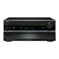
TX-SR876/SA876
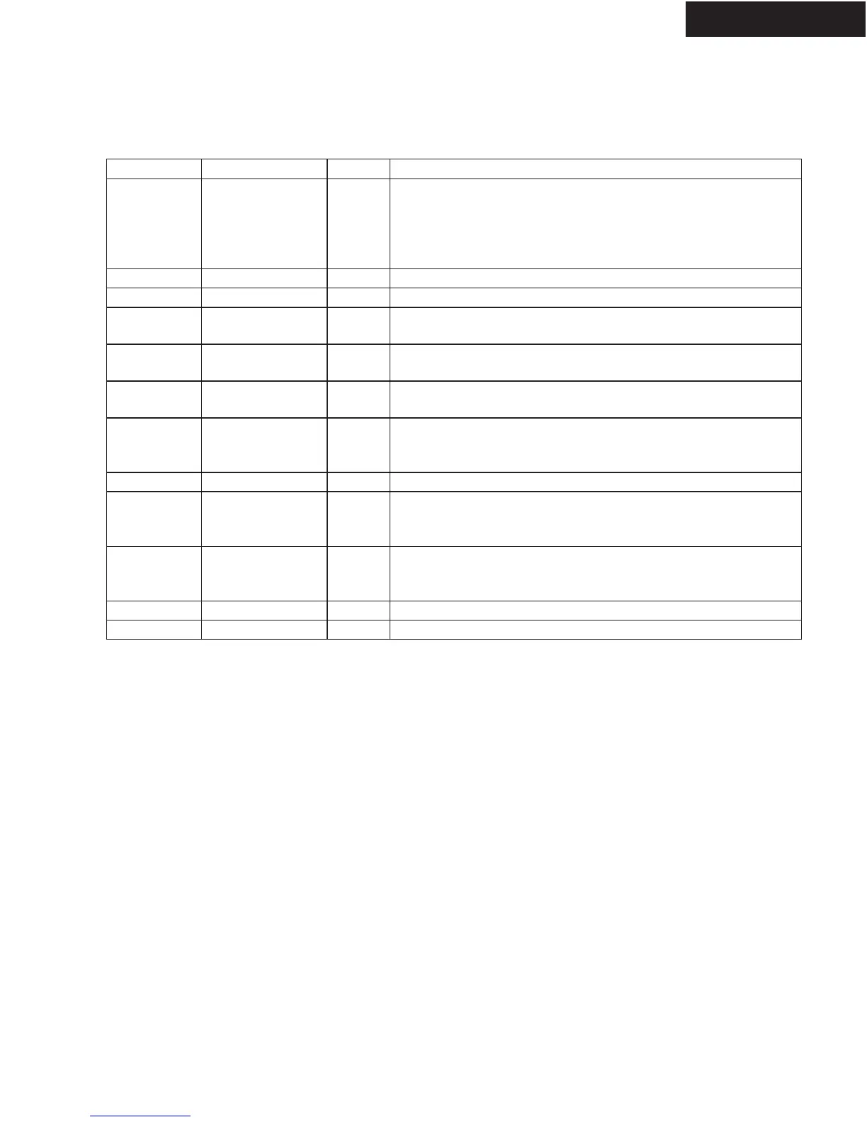
Pin No. Mnemonic Type
Function
15 SFL/SYNC_ O
UT
O SFL (Subcarrier Frequency Lock); this pin contains a serial
output stream which can be used to lock the subcarrier
frequency when this decoder is connected to any Analog
Devices digital video encoder. SYNC_OUT is the sliced sync
output signal only available in CP mode.
64 REFOUT O Internal voltage reference output.
65 CML O The CML pin is a common-mode level for the internal ADCs.
61, 62 CAPY1–
CAPY2
I ADC capacitor network.
68, 69 CAPC1–
CAPC2
I ADC capacitor network.
67 BIAS O BIAS is an external bias setting pin. Connect the
recommended resistor (1.35k ) between pin and ground.
86 HS_IN/CS_IN I Can be configured in CP mode to be either a digital HS input
signal or a digital CS input signal used to extract timing in a
5-wire or 4-wire RGB mode.
85 VS_IN I VS input signal used in CP mode for 5-wire timing mode.
79 DE_IN I DE_IN is a data enable input signal used in 24-bit digital
input port mode, for example,
24-bit RGB data from a DVI Rx IC.
35 DCLK_IN I DCLK_IN is a clock input signal used in 24-bit digital input
mode (e.g. 24-bit RGB data from a DVI Rx IC) and also in
digital CVBS input mode.
52 SOG I SOG is a sync on green input used in embedded sync mode.
77 SOY I SOY is a sync on luma input used in embedded sync mode.
 Loading...