26
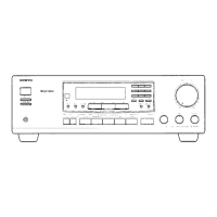
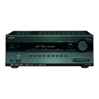
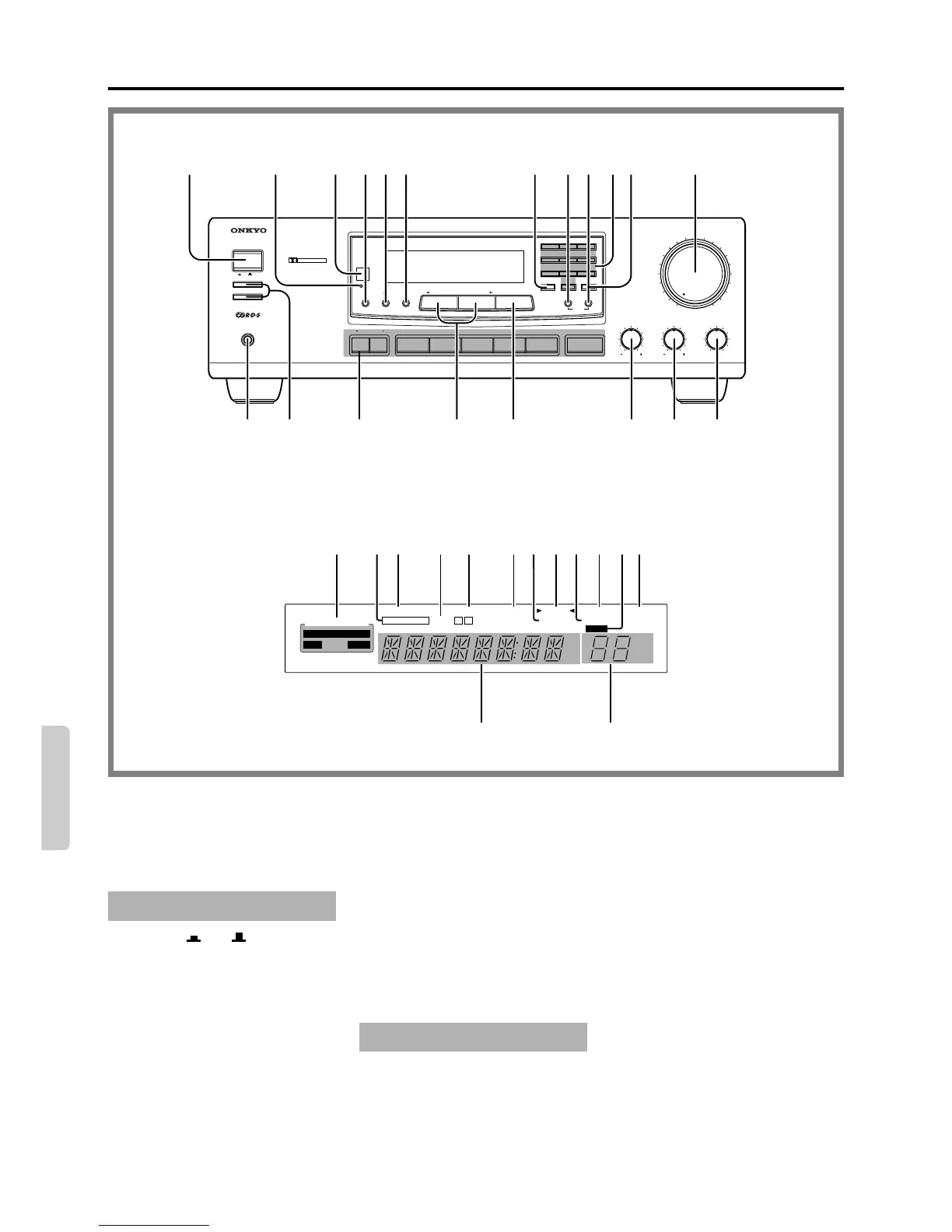
Control positions and names
BALANCETREBLEBASS
SYSTEM
ON
OFF
SPEAKERS A
SPEAKERS B
PHONES
DOLBY SURROUND
PRO
•
LOGIC
AMFMTAPE(MONITOR)TV/AUX PHONO
/1VIDEO VDP
/2
VIDEO VCR
MAXMIN
AUDIO VIDEO CONTROL RECEIVER
TX-SV353
LR
C D
MASTER VOLUME
STAND-BY
123
456
789
GROUP 0/10 SCAN
MEMORY
FM MUTE / MODE
CLEAR
CENTER
MODE
SURROUND
MODE
DELAY TIME
TUNING DIRECT TUNINGDOWN UP
256 12
20 19
18 1617 15 14 13
411
7 91 3 108
European model
OFF LIVE HALL
SPEAKERS A B FM MUTE
VIDEO 1 2 ON
OFF
TUNED
SLEEP
kHz
MHz
MIN
mSEC
CH dB
GROUP
A B C
BANK
+
–
DOLBY PRO LOGIC
SURROUND MODE
KARAOKE KEY CON
AUDIO MUTE
STEREO3-DB
MEMORY
R D S
TAPE MON.
n m
a c e h j lfdb g i k
Display
For more information about buttons or
knobs, turn to page number listed in the
brackets [ ].
1. System ( / ) switch
[9]
2. Stand-by/Received indicator [5]
3. Remote controller sensor [5]
4. Surround Mode button
[16, 17, 18]
5. Center Mode button [16, 18]
6. Delay Time button [18]
7. Group button [15]
8. Memory button [15]
9. FM Mute/Mode button [14, 15]
10. Number buttons [14, 15]
11. Scan button [15]
12. Master Volume control knob
[12, 18]
13. Balance control knob [12]
14. Treble control knob [12]
15. Bass control knob [12]
16. Direct Tuning button [14]
17. Tuning Up/Down buttons [14]
18. Input selector buttons [12, 19, 20]
19. Speaker selector buttons [12]
20. Headphone jack [13]
If there is a protective film on the surface
of the display which is making it difficult
to read the display, remove it.
a. Surround Mode indicators
b. Tape Monitor indicator
c. Speaker selector indicators
Front panel
ON OFF
Display
d. Video input selector indicators
e. Audio Mute indicator
f. FM Mute On/Off indicators
g. FM Stereo indicator
h. Tuned indicators
i. Memory indicator
j. Sleep indicator
k. RDS indicator (European models
only)
l. Group indicators
m. Multi function display
(Preset station/Sleep time/
Center & rear volume level/Delay
time)
n. Multi function display
(Frequency/Input selector)
 Loading...