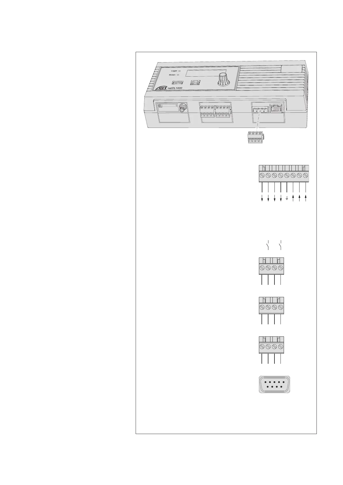
7.2 Overview of the locations of the screw terminal strips
and RS-232 interfaces
431 2
431 2
431 2
1 5
96
RS-232 interfaces
Communication COM 1 O-P O-P
COM 2 – Q-R
Serial sensor input
3)
G-H; J-K G-H; J-K; L-M
Connection of sensors
Screw terminal strip C, D + C … E +
G … K
2
)
G … M
2
)
4-20 mA outputs
Screw terminal strip S-T; U-V S-T; U-V; W-X
Status outputs
Screw terminal strip G-H; J-K G-H; J-K; L-M
U
Bat
0 V (GND)
U
Bat
(typ. +12 V)
U
Bat
0 V (GND)
OTT netDL … 500 1000
Voltage supply/
switching contacts
1)
Screw terminal strip N N
0 V
U
Bat
U
Bat
0 V
6 DSR
7 RTS
8 CTS
9 RI
1 DCD
2 RXD
3 TXD
4 DTR
5 GND
1)
max. 5 A
2)
G … K + G … M only with expansion cards
3)
only with RS-232 imput card
431 2 875 6
Switching contact
Switching contact
Switching contact
Switching contact
2
2
1
1
Fig. 7: Available positions for the
plug-in screw terminal strips.
The figure shows the OTT netDL 1000
unit without expansion cards.
Factory configuration
(without expansion cards):
OTT netDL 500: C, D + O-P
OTT netDL 1000: C-E + O-P
The specific configuration of your unit
including expansion cards as well as the
positions of the screw terminal strips/
RS-232 interfaces can be obtained from
the Factory Acceptance Test (FAT)
Certificate attached.
Please note: protect the feed line
of the voltage supply (screw terminal
strip N, contact 8) with a
safety fuse (10 A / fast)!
17