7.14 Connecting status outputs *
* OTT netDL with expansion analog output card
(refer to Chapter 2 "Ordering numbers and version code"
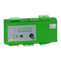
7.15 Connecting the power supply to the OTT netDL unit
Please note: protect the feed line of the voltage supply (screw terminal strip N,
contacts 6, 7 and 8) with a safety fuse (10 A /fast)
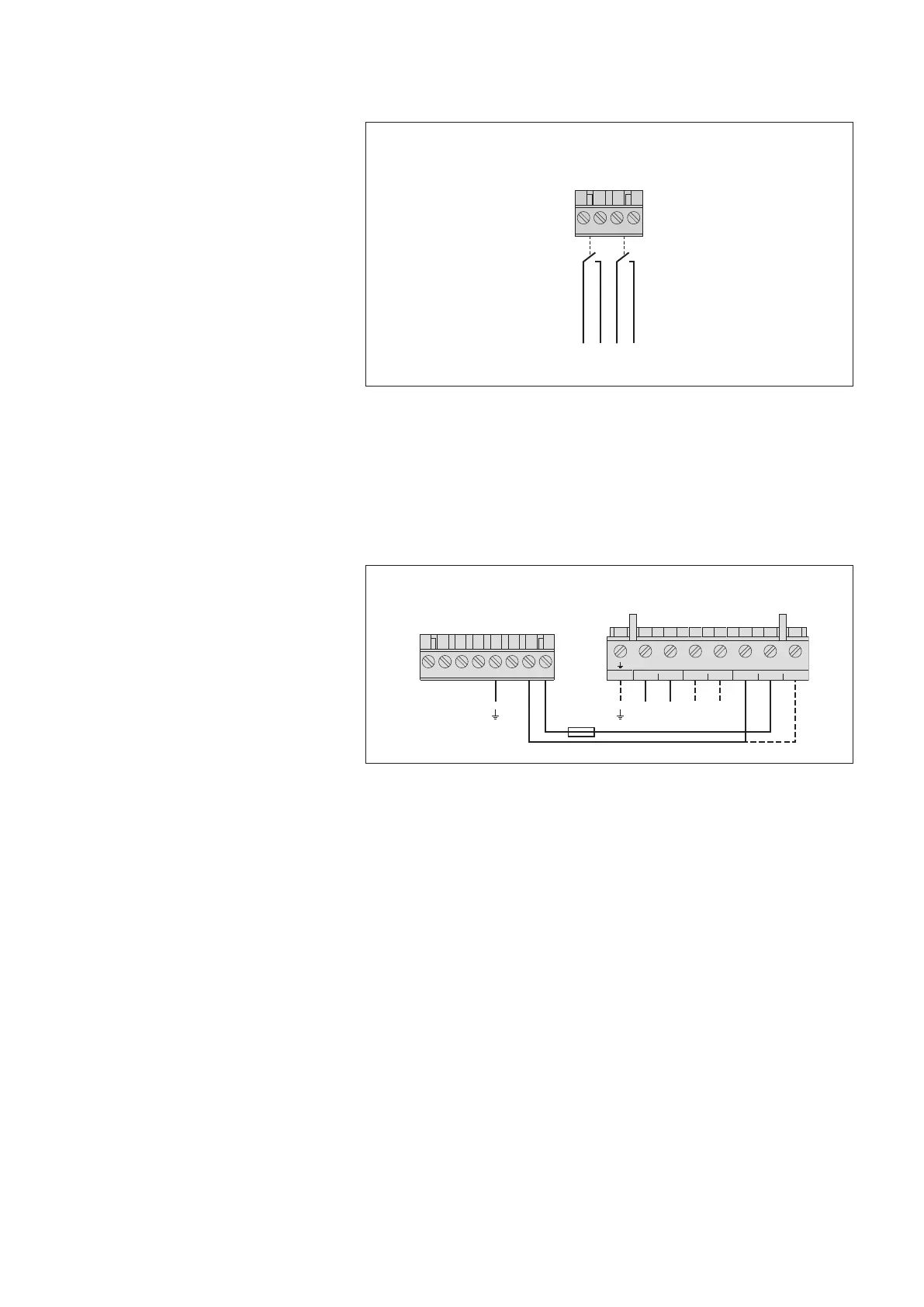
Fig. 22: Connecting the
OTT netDL status outputs.
Please note the maximum current capacity!
The two outputs are galvanically isolated
from each other and from the datalogger
(optical couplers).
431 2
Screw terminal strip G-K
1)
/ G-M
2)
Status outputs
max. 0.1 A/28 V DC
1
)
OTT netDL 500
2)
OTT netDL 1000
–
+
–
+
– 1 2
OUTPUTPANELAKKU
U
Bat
0 V
U
Bat
(+12 V)
Screw terminal strip N
Screw terminal strip PCU 12
4
31 2 875 6
10 A (F)
Fig. 23: Connecting voltage supply, e.g. to
an OTT PCU 12 power control unit. The OTT
PCU 12 is the OTT standard voltage supply.
Alternatively to PCU terminal 1 (load dis-
connect at a battery voltage of ≤ 7.5 V),
terminal 2 can also be used (load discon-
nect at a battery voltage of < 10.5 V).
Please note: A battery must always be con-
nected to the OTT PCU 12!
25