Insert the SIM card into the SIM card holder.
While doing so, please note the following:
– The gold-colored contacts of the SIM card are facing down. The beveled
edge of the SIM card is located in the front on the right-hand side!
– Do not touch the gold-colored contacts!
With the SIM card inserted, completely push the SIM card holder into the
OTT netDL unit, until it engages.
7.17 Connecting external communication equipment
If requested, a serial cable modem, a GSM modem (radio modem), or a satellite
communication unit can be connected to the OTT netDL unit.
Connect the RS-232 interface of the OTT netDL unit to a modem/satellite
communication unit using a commercially available modem connection
cable (accessory).
Optional: Connect the supply voltage of the modem using switching contacts
1 or 2 (screw terminal strip N 1-2 or N 3-4). (The modem is not permanently
powered ➝ reduces the current consumption of the station. The OTT netDL unit
enables power to the modem at specified time windows and/or when data
transfer is due.)
Note
An external voice-enabled modem for the voice announcer is always to be con-
nected to the COM 1 serial interfacel (refer to Fig. 4). When the COM 1 serial
interface is configured for the voice announcer, you cannot use this interface
for establishing a communication link.
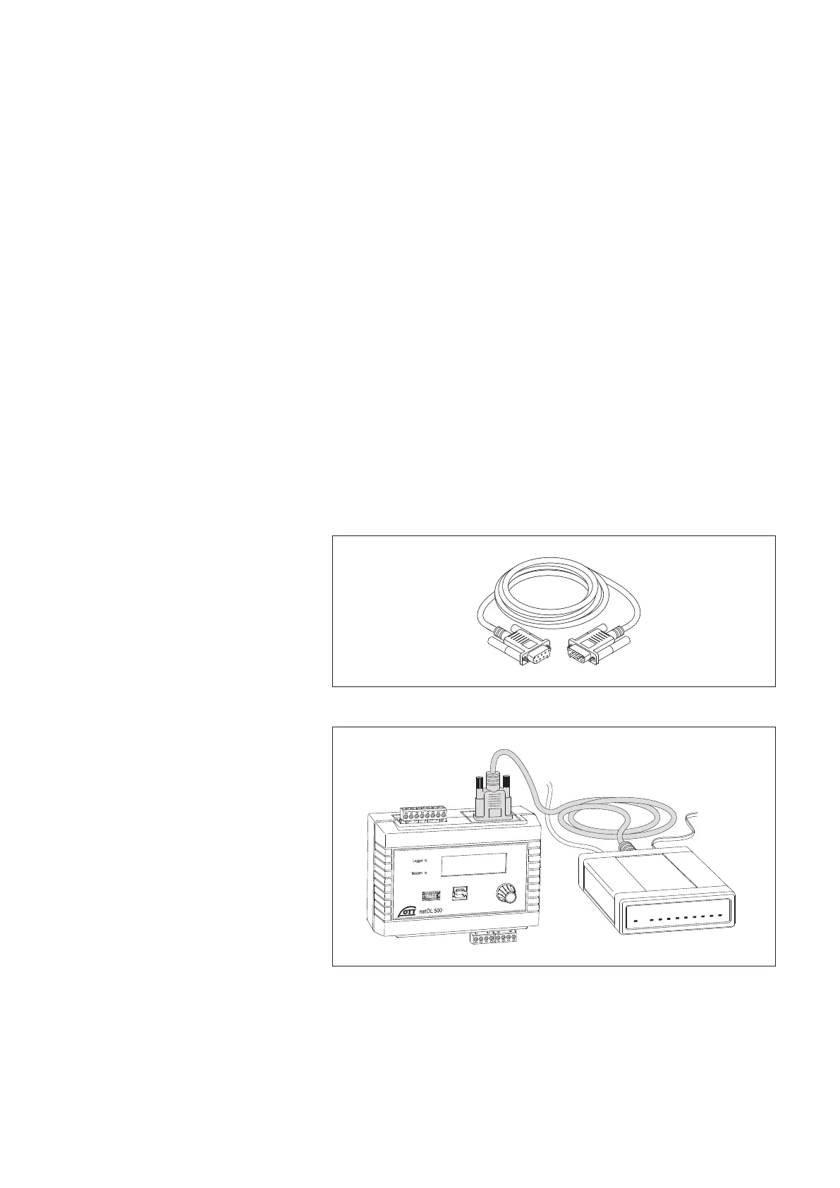
Fig. 26: Modem connection cable.
(9-pin Sub-D socket to 9-pin Sub-D connec-
tor; PIN 2 and PIN 3 each directly connected;
for position(s) of the RS-232 interface(s)
on the OTT netDL unit, refer to Fig. 4; for
pin assignment of the RS-232 interface,
refer to Fig. 7).
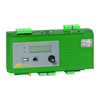
Fig. 27: Connecting serial modem
to the OTT netDL unit via modem
connection cable (figure shows the
OTT netDL 500 unit, proceed the same
way for the OTT netDL 1000 the unit).
27