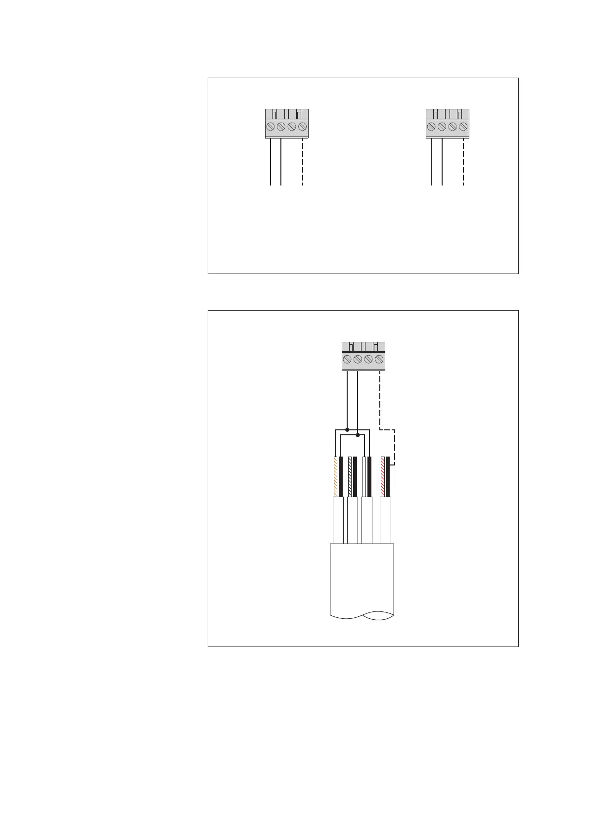
7.3 Connecting sensors having an RS-485 interface (2-wire)
RS-485 GND
RS-485 GND
Screw terminal strip C
RS-485 B
RS-485 A
431 2
RS-485 A
RS-485 B
431 2
general OTT Kalesto, OTT CBS,
OTT SLD, OTT Sonicflow
Fig. 8: Connecting RS-485 interface sensors
to the OTT netDL unit (e.g. OTT Parsivel Pre-
sent Weather Sensor, OTT RLS radar sensor,
or third-party sensors providing Modbus
communication protocol). Possible com -
munication protocols: SDI-12 via RS-485,
OTT protocol, or Modbus.
If multiple sensors are to be connected to
an OTT netDL unit, it is to be done using an
RS-485 bus topology. Different communica-
tion protocols are not allowed to be used on
the same RS-485-bus!
Further information can be found in the
operating instructions of the respective sensor.
The GND connection represented by the
dashed line is necessary only in case the
sensor and the OTT netDL unit are supplied
from different power supplies.
Screw terminal strip C
431 2
RS-422
Power supply
+ 12 V
GND
Rx+
Rx–
Tx+
Tx–
RS-422
not used
RS-422
OTT SLD
RS-485 B
RS-485 GND
RS-485 A
Abb. 9: Connecting the side looking
doppler OTT SLD unit to the OTT netDL
using the RS-485-interface
(SDI-12 via RS-485).
The GND connection represented by the
dashed line is necessary only in case the
OTT SLD and the OTT netDL unit are sup-
plied from different power supplies.
18