7.13 Connecting 4-20 mA outputs *
* OTT netDL with expansion "analog output card“
(refer to Chapter 2, "Order numbers and version code")
Screw terminal strip
S … V
1)
/ S … X
2)
4
31 2
Screw terminal strip
S … V
1)
/ S … X
2)
4
31 2
+
–
4 … 20 mA +
4 … 20 mA –
R
Load
external
s
upply
≤ 28 V
R
Load
4 … 20 mA +
4 … 20 mA –
–U
Bat
+U
Bat
Current loop provided
internally
Current loop provided
externally
1)
OTT netDL 500
2)
OTT netDL 1000
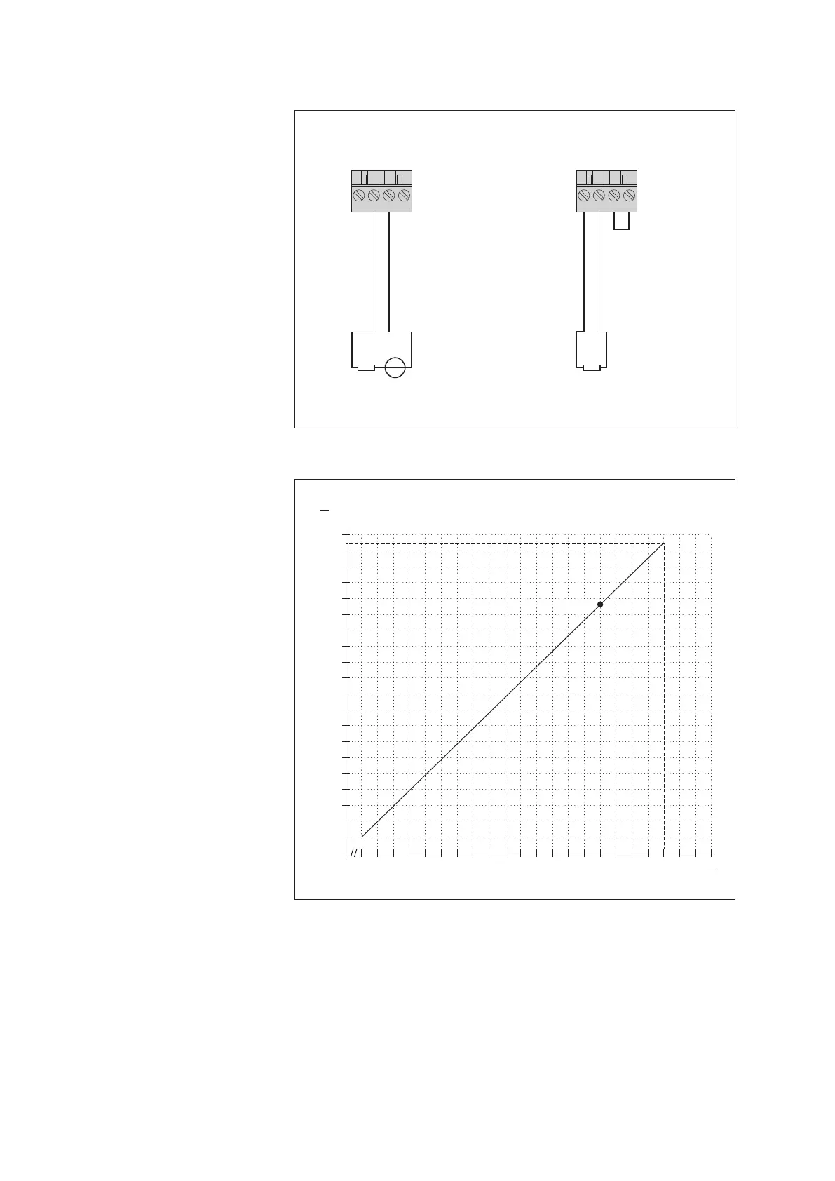
Fig. 20: Connecting the OTT netDL
4-20mA outputs.
Left: Connection schematic with
external supply of the current loop.
Right: Connection diagram with internal
supply of the current loop.
Make absolutely sure that the
burden (R
B
urden
) in the current
loop is correctly dimensioned!
Refer to Figure 21.
With the internally powered current loop,
take into account that the actual supply
voltage (U
bat
) may be lower than the rated
supply voltage.
Fig. 21: Diagram for determining the maxi-
mum load resistance vs. supply voltage.
The load resistance (burden + ohmic resis-
tance of the connection leads) connected to
the OTT netDL unit must not exceed a spe-
cific maximum value. This value depends on
the level of the supply voltage. When the
load resistance is higher, the output current
can no longer be evaluated. Smaller load
resistances are allowed.
Example: 24 Volt supply voltage
➝ max. load resistance 780 ohm. For a
load resistance of up to 780 ohm, the
OTT netDL unit provides output current
based on the measured value.
Minimum supply voltage: 9 V
Maximum supply voltage: 28 V
10
15
20
25
30
U
V
100
0
200
300
400
500
600
700
800
R
Ω
900
1000
Example
24
 Loading...