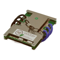
Figure 2.4.2.2: Balance lead connector and pinout, for 24V BMS
Spin the nuts on as you go. Suggest torque is 20 ft-lbs (27 Nm), or “Nice and snug.”
Warning: Do not pinch the balance wires under a nut! Instant smoke!
2.4.3 Prepare BMS
Place the BMS in its desired location. Ideally, it should be mounted vertically, either attached to the battery
cells, or mounted as close to them as possible. Ensure that it is mounted within reach of Cell #1’s negative
terminal (it should be labeled BC0).
If the B- wires do not reach the BC0 terminal, then they must either be lengthened, or replaced with a longer
cable. Longer, thicker pigtail cables are optional at the time of purchase.
2.4.3 Add BMS
Mount the BMS to the pack. Double-sided foam tape and/or zip ties can be used. Wire the BMS’s blue B-
pigtail cable to the Cell #1 BC0 terminal. Wire BMS’s C- terminal to the load’s negative connection (or, more
ideally, through a power distribution block as described in Section 2.2.1)
2.4.4 Positive Load Connection
Connect the positive-most connection on the battery to the load’s positive connection (or, more ideally,
through a power distribution block as described in Section 2.2.1).