Figure 2.4.6.1, diagram of a switch wired to the pigtail lead
Any switch will do here, as long as it’s not momentary. Toggle switches or rocker switches are recommended.
When soldering your switch to the lead, use heat-shrink tubing over the connections.
If you do not wish to use the external switch, you may either leave the included jumper in place, or configure
the BMS to not use the switch (see Section 3.4.1 for instructions).
2.4.7 Connectivity
For systems with multiple BMSs and battery packs, it may be desirable to use an external battery monitor to
visualize the complete system as a single unit.
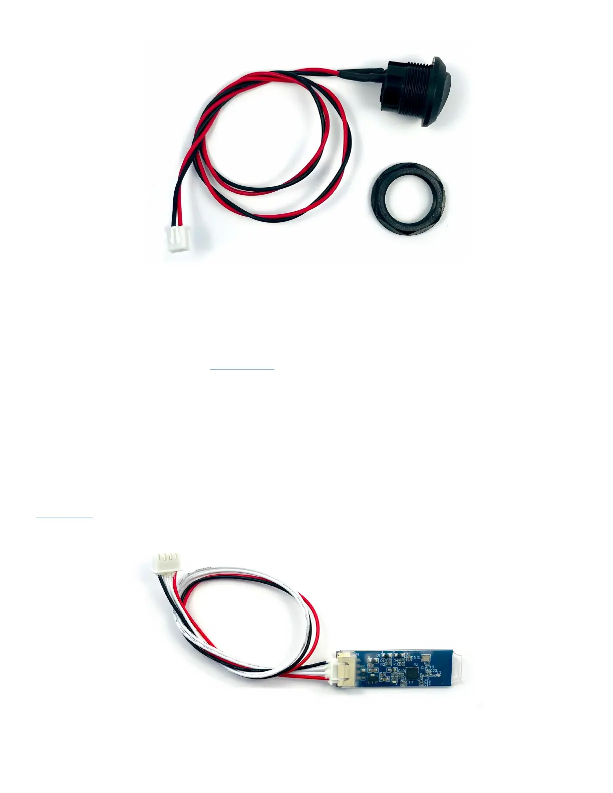
2.4.7.1 Bluetooth Module
The Bluetooth module is an optional accessory that may be used to configure and monitor the BMS. See
Appendix E for instructions on using the iPhone or Android app.
To use, simply plug the 4-pin connector into the BMS. The BMS must be connected to the battery, with the
balance lead connected in order for the Bluetooth module to operate.