49/78 06/02/2008
Parts
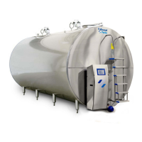
The table below provides an overview of the parts of the IB cooling system:
High and low pressure switch
Thermostatic expansion valve
High pressure switch (option)
Solenoid valve (not on OM/IB)
Operation of the IB cooling system
The table below describes the operation of the IB cooling system.
The cooling unit builds up a bank of ice around the copper evaporator
pipes (10) – see figure 1.
The thickness of the layer of ice around the pipes is controlled by an
ice thickness regulator. When the layer of ice is sufficiently thick, the
cooling unit is automatically switched off. This prevents one block of
ice being formed.
When the milk cooling is activated, the ice water is sprayed (d) by the
ice water pump (c) via the spray tubes (a) along the outer wall of the
milk tank (b). The water absorbs the heat of the milk. That is how the
milk is cooled.
The heated water flows back into the ice storage tank and makes sure
that the ice melts.
When the ice thickness regulator detects that the layer of ice is
becoming too thin, the cooling unit is reactivated so that there is
always a sufficient stock of ice.
Operation of the cooling unit
The compressor (2) extracts the cooling gas out of the evaporator (10),
under low pressure and pumps it under high pressure to the condenser
(3).
The fan sucks air over the cooling fins of the condenser, so that the
gas in it condenses into a liquid.