55/78 06/02/2008
Voltage control relay
The H3US control realy controls the 3-phase network:
- overvoltage between phases
- undervoltage between phases
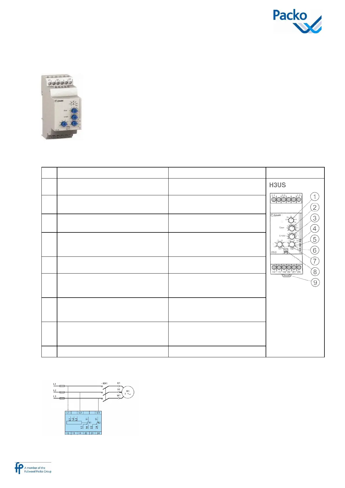
Description
Voltage range selection switch (220-380-
400-415-440-480V)
Select the nominal mains voltage
(Un)
Potentiometer for overvoltage setting,
+2 +10% (Over)
Set the maximum threshold
Potentiometer for undervoltage setting,
-2 -12% (Under)
Set the minimum threshold
Relay output status (yellow) LED. Over
threshold (R1)
Is lit when the voltage exeeds the
maximum threshold after the set
delay (8)
Relay supply status (green) LED. Un
Is lit when the voltage lies between
the minimum and maximum voltage
Relay output status (yellow) LED. Under
threshold (R2)
Is lit when the voltage exeeds the
minimum threshold, after the set
delay(7)
Threshold time delay adjusting
potentiometer (0.3 30s): undervoltage
(Tt2)
Set the time delay for undervoltage
Factory settings: 4 seconds
Threshold time delay adjusting
potentiometer (0.3 30s): overvoltage
(Tt1)
Set the time delay for overvoltage
Factory settings: 4 seconds
35 mm rail clip-in spring
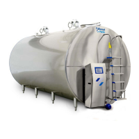
Diagram