ILF 33/44/55 Installation Manual
Rev 1.1 31
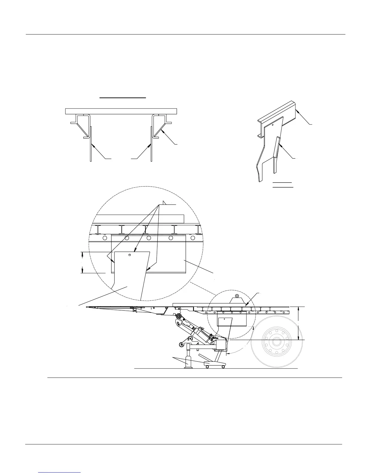
2. Place the mount tube in the predetermined position, keeping the given maximums and minimums
dimensions in mind. Support the mount tube with a rolling floor jack or a similar device to position
the mount tube. Make sure the mount tube is squared 90-degreed, vertically and horizontally, to the
trailer. Use a minimum of 8” overlap between the mount plates and sub-frame channel. Clamp
mount plates to sub-frame to prevent any misalignment before welding.
90°
F-Dimension
Support
Jacks
3" channels
Sub Frame
Channel
Sub Frame
Channel
Rear View of Trailer
Recommended Support
Plates along sub-frame
channel for strength
(Not supplied by Palfinger)
Mount Plate
Sub-Frame
Channel
Street Side
Mount Plate
8.00"
Overlap
Mount Plate
3/16"
Mount
Plates
3. Proceed to the electrical installation, Section 9.