2000 - FIRE ALARM SOLUTIONS TECHNICAL DESCRIPTION
15
4.1. INTERNAL CONNECTIONS
The batteries and power supply are connected to the main board, which handles the charging of the batteries.
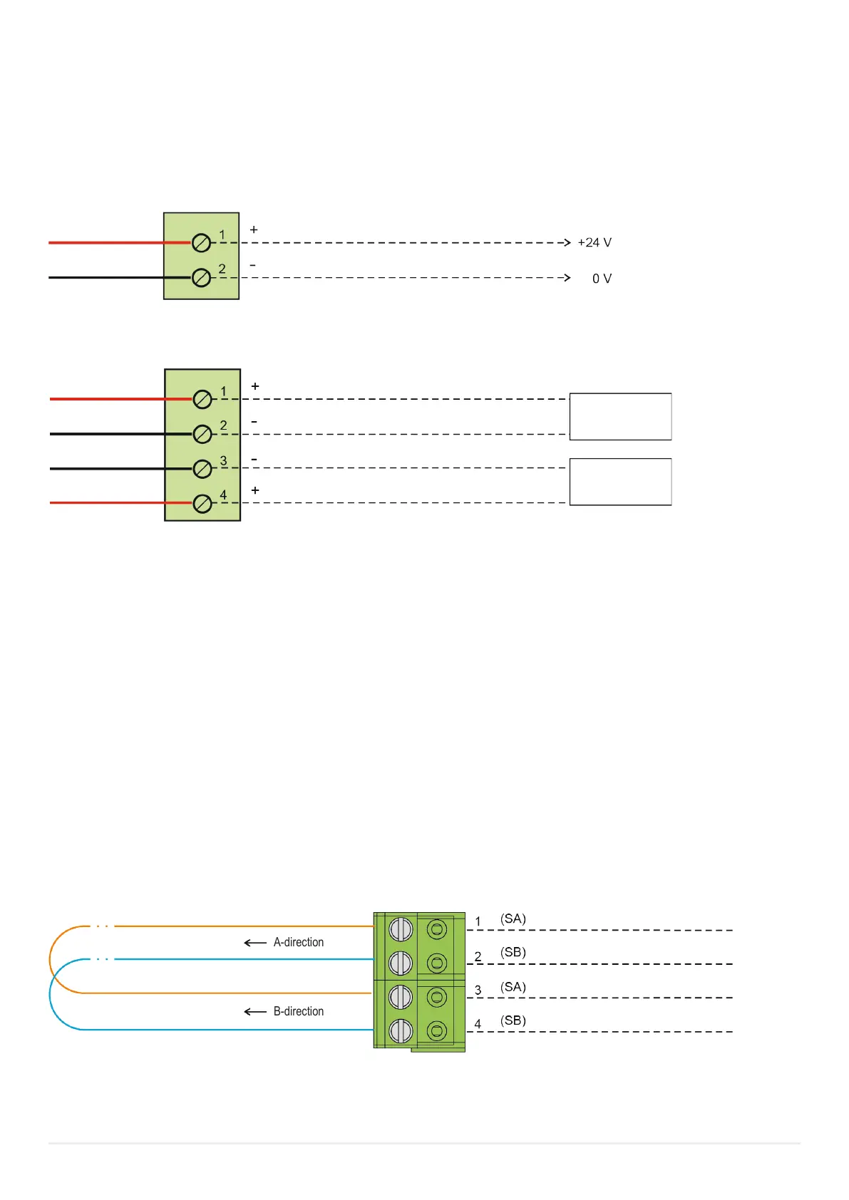
Plug-in connector J1 Power supply
4.2. COM LOOP
EBLOne has one COM loop. On the COM loop, up to 253 addressable COM loop units can be connected (address 001-253). Re-
garding type and number of COM loop units in relation to the cable length / type, see chapter “COM loop cable length” and
“Current consumption” in EBLOne Planning instructions.
Each COM loop unit has a COM loop address (for example 123) also designated Technical address.
Each alarm point and zone line input has a re alarm presentation number (Zone-address), for example 001-01.
See EBLOne Operating Instructions for more information.
The CIE sends data by changing the polarity on the loop.
Voltage on the loop terminals: 24.0 V ± 1.5 V.
The COM loop is LPS output (Limited Power Source). The COM loop outputs has maximum effect below 100W.
Maximum loop current: 350 mA.
COM loop is connected to terminal block J4: 1-4.
A-direction
B-direction
Battery charger
Plug-in connector J2 Batteries
Battery charger