Do you have a question about the Panasonic EBL128 and is the answer not in the manual?
Unit that generates a fire alarm, e.g., detector or manual call point.
Detector with two statuses (normal or fire alarm) connected to a zone line.
Unit with built-in address for individual identification and handling.
Cable connecting addressable Panasonic COM loop units, forming a closed loop.
Installation-unique data programmed via EBLWin, including alarm texts and outputs.
Software that makes the EBL128 microprocessor work; can be upgraded.
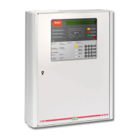
Description of the EBL128 as an intelligent fire alarm Control and Indicating Equipment.
Details of the EBLWin PC software for programming and commissioning.
Role of the FBP for fire brigade personnel to view alarm and system status.
Role of the CP for system communication, tests, and maintenance.
Details of LED indicators on the FBP for alarm and system status.
Description of push buttons on the FBP for controlling system functions.
Details of LED indicators on the CP for system status.
Description of keypad buttons on the CP for system operation and access.
Description of the EBL128 LCD display and its information presentation.
Details on the EBL128 LCD backlight operation and power saving.
Table showing the priority order of events and alarms displayed on the LCD.
Functionality of the 'Silence Alarm devices' button (P3) for disabling alarm devices.
Operation of the external key switch for silencing alarm devices.
Activates all sounders (alarm devices) to turn ON steady.
Acknowledges an Alert Annunciation alarm, similar to AA units.
Disables all zones in fire condition.
Describes functions of German push-buttons like 'ÜE prüfen' and 'Brandfall Steuerungen ab'.
Explains indications like 'Brandfall Steuerungen ab' and 'Akustische Signale ab' on German panels.
Details on the buzzer behavior and 'ÜE ab' button for routing equipment.
Information on output disablements and their display in c.i.e. and FAT.
Indication of the 'Door open' status via LED (L10).
Behavior of Fire brigade tx and Fault tx outputs when the door is open.
Functionality to silence the buzzer when the EBL128 door is open.
Usage of technical address for programming COM loop units and identifying faults.
Format of presentation numbers (NN-NN) for identifying alarm points and zones.
Alarm triggered at a lower level than fire alarm for early detection.
Details on fire alarm types, activation, and display presentation in EBL128.
Covers key cabinet alarms and quiet alarms used for fan control.
Procedures for resetting pre-warning and alert annunciation alarms.
Methods for resetting fire alarms: All, Single, and Single with auto-disablement.
Reset procedures for coincidence, heavy smoke/heat, key cabinet, quiet alarms, and AAF.
Comprehensive alphabetical list of all possible fault messages and their causes.
Steps for acknowledging faults, including using menus and LEDs.
Methods for programming and auto-generating Site Specific Data (SSD).
Steps for downloading the programmed SSD into the EBL128 unit.
Procedure for downloading custom alarm texts to the EBL128 display.
Procedure for upgrading the EBL128 software via EBLWin.
Instructions for downloading earlier software versions or to display units.
Explanation of different restart types (cold/warm) and their effect on data.
Accessing and using the Boot menu for restart or memory erase.
Procedures for disabling and re-enabling zones and specific alarm points.
Steps to manage outputs, alarm devices, and routing equipment for disablement.
Managing alarm devices and routing equipment outputs for disablement and re-enablement.
Procedure for disabling and re-enabling the alert annunciation function.
Procedure for setting the system date, time, and weekday.
Settings for automatic daylight saving time changes based on convention.
View disablements applied to zones, addresses, and outputs.
Displaying sensor values, performance factors, and algorithms.
Information on sensors needing service and system technical warnings.
Accessing the event log and viewing software/firmware version and alarm counter.
Calibrating supervised outputs and enabling sensitive fault detection mode.
Using service mode for COM loop communication and display statistics.
Displaying current consumption, statistics, and site-specific data.
Activating address setting mode for Display Units (DU) connected to RS485.
Procedures for disconnecting and reconnecting COM loops and zone line inputs.
Acknowledging service signals and restoring sensor values to default.
Testing alarm devices and performing a safe shutdown of the control unit.
Manually activating zones/addresses in alarm mode and activating outputs.
Viewing activated interlocking outputs/inputs and activating them.
Resetting, disabling, and re-enabling interlocking outputs.
| Brand | Panasonic |
|---|---|
| Model | EBL128 |
| Category | Security System |
| Language | English |