Panasonic Eco Solutions Nordic AB
MEW01623 Rev: - EBL128 Operating Instructions V2.0.x
16
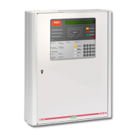
5 LED indicators and push buttons
LEDs and push buttons can vary according to configuration /
convention / country / language.
See also Figure 2, page 14.
LED indicators on the Fire Brigade Panel (FBP)
Fire (5 red)
Blinking (0.4/0.4s)
Fire alarm (also heavy smoke/heat alarm, Quiet alarm & key
cabinet alarm)
3
Alarms queued (2 red)
Blinking (0.4/0.4s)
More than one unit / zone have generated fire alarm.
Output(s) activated for extinguishing equipment.
4
Output(s) activated for fire/smoke ventilation equipment.
4
Output activated for Fire brigade tx (routing equipment)
and/or corresponding programmable output(s) of type routing
equipment.
4
Test of routing equipment in progress (see menu H1).
Power on, i.e. EBL128 is power supplied via the rectifier or
the backup battery.
(FBP push buttons on next page)
In the New Zealand convention also "Acknowledged alarm" (ACK).
L3, L4 and L5 can as an alternative be programmed to indicate when a
programmable input is activated, i.e. input trigger condition "Extinguishing
system released", "Activated fire ventilation" and "Activated routing
equipment" respectively (e.g. L5 can be turned on when a programmable
input is activated by an activated routing equipment output). L5 is turned on
until all fire alarms are reset.