Panasonic Eco Solutions Nordic AB
MEW01623 Rev: - EBL128 Operating Instructions V2.0.x
18
(CP LED indicators on next page)
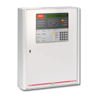
LED indicators on the Control Panel (CP)
Fault(s), i.e. not acknowledged fault(s) and/or
acknowledged but not corrected fault(s).
Something is disabled / disconnected via a menu or
automatically via "Single encapsulated reset"
7
.
One or more zones are in "test mode".
A door is open (in EBL128 or an ext. FBP).
11
12
Störung Löschanlage
(yellow)
An input with trigger condition "Extinguishing system
fault" is activated (true).
Fault tx activated (yellow)
Output activated for Fault tx (routing equipment), i.e.
one or more not acknowledged faults.
Test of routing equipment in progress (see menu H1).
One or more sensors have reached the service level.
See menu H4/U4.
12
Leitungsstörung
Löschanlage (yellow)
Short-circuit or cut-off (open circuit) on a supervised
input OR a supervised output type "Extinguishing".
Fault / Disablements
Alarm devices (yellow)
One or more outputs (type Alarm device) are disabled.
Blinking: One or more supervised outputs (type
Alarm device) have generated fault(s).
13
EBL128 is not running (because of S/W, CPU or
memory fault).
14
Fault / Disablements
Fire brigade tx (yellow)
Output for Fire brigade tx (routing equipment) is
disabled via menu (H2/B10) or via an open door.
11
Blinking: Routing equipment power supply output
15
or one or more supervised outputs (type Routing
equipment) have generated fault(s).
16
See also chapter "Door open", page 36.
L10 and L12 have different functions on the German front.
This is also valid when EBL128 has no "contact" with a unit with such an
output, e.g. 3377, 3378, 3361, etc.
The LED is turned on during restart and stays on for restart code other
than 00, 03 or 25 until the fault is acknowledged.
Main board terminal block "J1:11-12".
This is also valid when EBL128 has no "contact" with a unit with such an
output, e.g. an I/O unit 3361, etc.