2000
- FIRE ALARM SOLUTIONS TECHNICAL DESCRIPTION
22
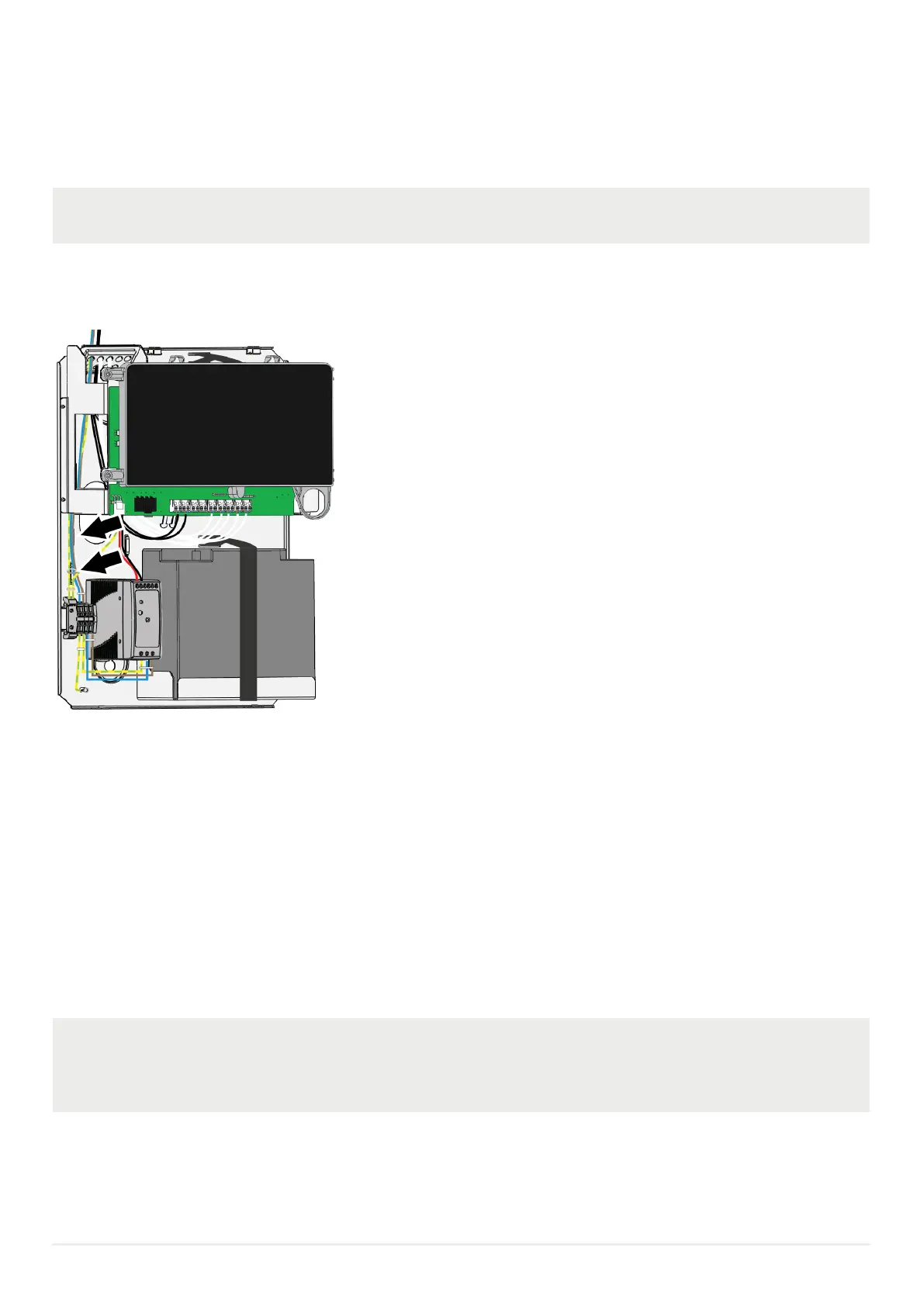
5.1. WIRING
a) Connect the battery cables to the battery / batteries.
When only one battery is used, connect both battery cables from plug-in connector J2 to the battery.
b) Make the cable connections. Pull the cables through the cable gland on top of the chassis or through the hole in the back of
the chassis.
c) Use cable ties to fasten the 230 VAC cables to the two cable holders in the chassis, see arrows.
5.2. COMMISSIONING
Before you connect the power supply to the control unit, all other cable connections shall be made. Check once more that they are
correct.
A tip! Measure the resistance of each loop wire (SA & SB respectively) before turning on the power. Check that the SA-wire that
goes out on terminal J4:1 comes back at terminal J4:3 and so on. If the loop has short circuit isolators, only the SB-wire can be
measured.
Also measure the resistance between the loop wires and 24V, 0V and Earth (J1:3,2,1). The resistance should be very high (mega
ohm).
a) Connect the rectier to the mains (230V AC). A cable tie shall be mounted to keep the mains wires well separated from the
24V DC wires.
It shall be connected to a household removable fuse for the re alarm CIE only, via a two-way circuit
breaker. National regulations must always be followed. The mains cable shall be securely clamped and
the wires shall be as short as possible. The mains safety earth (ground) shall, however, be longer than the
other wires, to ensure that it is the last to be disconnected if the mains cable clamp should fail.