3D Signal Recording and Playback: Connections
41
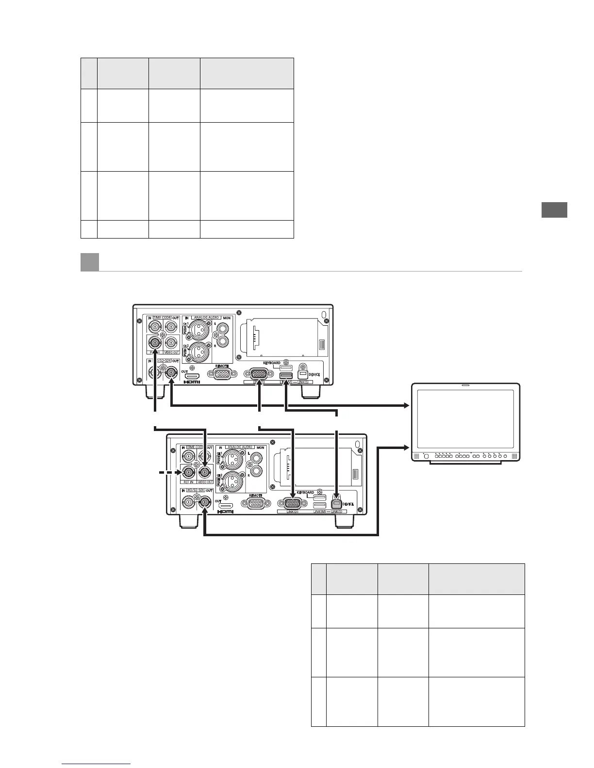
3D Signal Recording and Playback
Connect the master and slave units together with
a USB 2.0 cable between the LINK (USB) ports,
an RS-422A/D-SUB9P cable between the LINK
(D-SUB) connectors, and BNC cables between
the synchronizing jacks, as illustrated. With these
connections, setting the units to 3D REC/PB mode
enables 3D playback. During playback, the 3D
left-eye image is output from the master unit’s (L)
SDI output jack, and the 3D right-eye image is
output from the slave unit’s (R) SDI output jack, for
3D (simultaneous) viewing on the 3D monitor.
Master
(L) Jack
Slave
(R) Jack
Remarks
A REF IN VIDEO
OUT
BNC cable
B LINK (M)
USB
Type A
LINK (S)
USB
Type B
USB 2.0 cable
C LINK (D)
9P D-SUB
LINK (D)
9P D-SUB
RS-422A-
compliant cable,
Length 1 m or less
D SDI IN SDI OUT BNC cable
Discrete Left/Right Signal Output Connection Example
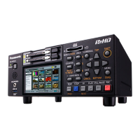
AG-HPD24 (Slave/3D-R)
AG-HPD24 (Master/3D-L)
SDI Output
3D Monitor
SDI Output
ASync Signal
C LINK (D-SUB)
B LINK (USB)
An input reference
signal can be
connected to the
REF IN jack on the
slave.
Master
(L) Jack
Slave
(R) Jack
Remarks
A REF IN VIDEO
OUT
BNC cable
B LINK (M)
USB
Type A
LINK (S)
USB
Type B
USB 2.0 cable
C LINK (D)
9P D-SUB
LINK (D)
9P D-SUB
RS-422-compliant
cable, Length 1 m
or less
 Loading...