20
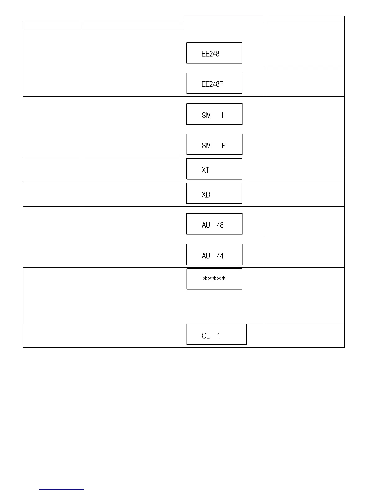
RTSC Return in XP
(A & V)
L1 input signal is encoded (XP), decoded
(XP) and output decoded signal to external
without DISC recording and DISC playback.
Initial mode: EE2/ Interlace/ XP/
Audio 48kHz
Press [1] [3] in service mode.
Switch Interlace/Progressive Press [1] [4] in RTSC Return XP
mode.
*I/P are switched alternately.
I/P Switch Switch Interlace and Progressive in EE mode.
*Initial setting is “Interlace”.
*This command is effective during executing
“White Picture Output”, “Magenta Picture Out-
put” and “RTSC Return in XP (A & V)” modes.
Initial mode is Interlace
Switch Interlace/Progressive
Press [1] [4] in I/P Switch mode.
*I/P are switched alternately.
Audio Mute (XTMUTE) Check whether mute is applied normally by
the timer microprocessor.
Press [2] [1] in service mode.
Audio Mute (XDMUTE) Check whether mute is applied normally by
the Digital P.C.B..
Press [2] [2] in service mode.
Audio Pattern Output The audio pattern stored in the internal mem-
ory is output
(Lch: 1kHz/-18dB)
(Rch: 400Hz/-18dB)
*Audio sound clock switching operation of
DAC can be confirmed by sub command [2]
[4].
Initial mode (Audio 48kHz) Press [2] [3] in service mode.
Audio 44.1kHz/48kHz switching Press [2] [4] in Audio Pattern Output
mode.
*48 kHz / 44.1 kHz are switched
alternately.
Laser Used Time Indic-
tion
Check laser used time (hours) of drive.
l(*****) is the used time display in
hour.
lLaser used time of DVD/ CD in
Playback/Recording mode is
counted.
Press [4] [1] in service mode.
Delete the Laser Used
Time
Laser used time stored in the memory of the
unit is deleted.
Press [9] [5] in service mode.
Item FL display Key operation
Mode name Description (Remote controller key)
 Loading...