Panasonic Eco Solutions Nordic AB
MEW01622 Rev: - EBL128 Planning Instructions V2.0.x
158
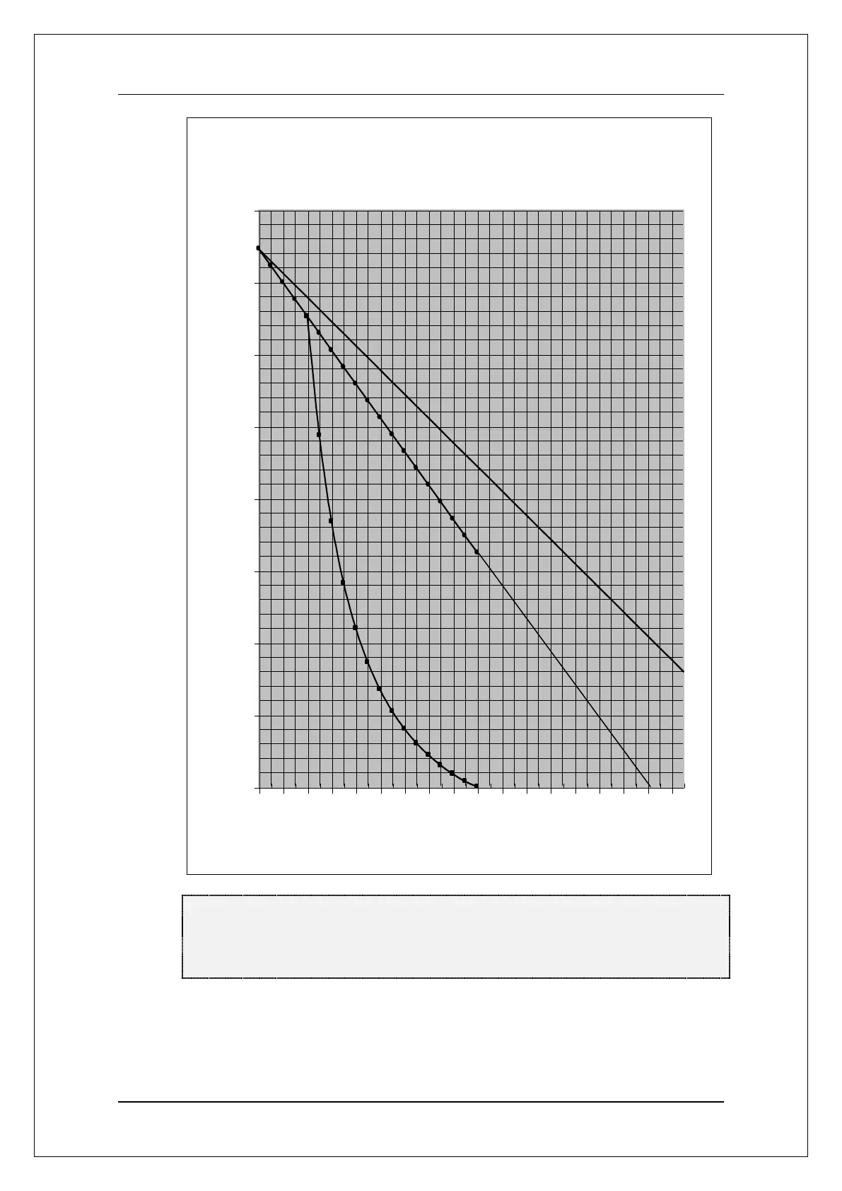
Maximum conductor resistance
5
10
15
20
25
30
35
40
45
0 40 80 120 160 200 240 280 320
Total COM loop unit current consumption
Figure 30. Graphs showing the total conductor resistance in relation to the
COM loop units' total current consumption. NOTE! The graphs start at "0
mA" but graph 1 ends at "320 mA" and graph 2 ends at "350 mA". End of
graph = max. allowed loop current.
NOTE! The total conductor resistance (ohm) = L conductor (ohm) +
C conductor (ohm).
 Loading...