Panasonic Eco Solutions Nordic AB
MEW01622 Rev: - EBL128 Planning Instructions V2.0.x
15
4 Control & Indicating Equipment
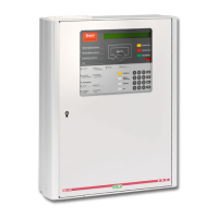
Figure 1. The EBL128 Control & Indicating Equipment (4550).
Depending on country, convention, configuration, etc. the look,
language and functions might vary. Figure 1 shows an EBL128 with
English front. The metal housing consists of a wall mounted chassis
on which a removable skin, incl. the door, is attached. This makes the
installation and service very easy.
EBL128 is in its basic configuration equipped with:
Main board 4556 with:
o One COM loop (0) to which the loop units are connected.
Connections and more information, see drawing 128-21.
o Two programmable supervised voltage outputs (S0-S1).
Default programmed as outputs for alarm devices.
Connections and more information, see drawing 128-22.
o One programmable relay output (R0). Default programmed as
output for fire alarm routing equipment (Fire brigade tx).
Connections and more information, see drawing 128-23.
o One not programmable relay output for fault routing equipment
(Fault tx). Connections and more information, see drawing
128-23.
o One programmable input (I0). Supervised when required.
Connections and more information, see drawing 128-22.
o Two 24 V DC power supply outputs (for routing equipment and
external equipment respectively). Connections and more
information, see drawing 128-22.
 Loading...