Do you have a question about the Panasonic KX-TG4221N and is the answer not in the manual?
Caution regarding the risk of explosion if the battery is replaced incorrectly.
Block diagram illustrating the main components and connections of the base unit.
Detailed explanation of the circuit operations within the base unit.
Block diagram illustrating the main components and connections of the handset.
Detailed explanation of the circuit operations within the handset.
A flowchart to diagnose and resolve common issues with the telephone system.
Step-by-step instructions for disassembling the base unit and handset.
Component view of the main printed circuit board for the base unit.
| Brand | Panasonic |
|---|---|
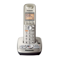
| Model | KX-TG4221N |
| Category | Answering Machine |
| Language | English |