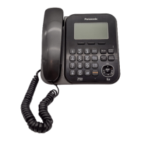
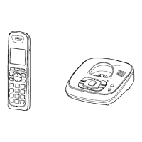
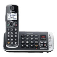
Do you have a question about the Panasonic KX-TG4732B and is the answer not in the manual?
Precautions for service technicians regarding repair work to prevent hazards.
Risks associated with incorrect battery replacement and recycling information.
Information on lead-free solder usage, melting points, and precautions.
Explanation of the US-DECT system, frequency range, and frame format.
Details on the Time Division Duplex (TDD) frame format used in the system.
Explanation of the Time Division Multiple Access (TDMA) system and handset links.
Describes the signal reception and transmission flow in radio parts.
Illustrates the main block diagram of the base unit.
Shows the block diagram for the RF part of the base unit.
Explains the operational circuit of the base unit, including BBIC, Flash Memory, and EEPROM.
Details the functions of the Base Band IC, including voice message, DTMF, and Caller ID.
Describes the power supply and reset circuit operation.
Explains the charge circuit operation for the AC adaptor.
Details the telephone line interface circuit functions and operation.
Explains circuits for detecting parallel connections and auto-disconnecting.
Describes Caller ID and Call Waiting Caller ID functions and formats.
Shows the block diagram for the RF part of the handset.
Explains the operational circuit of the handset, including BBIC, EEPROM, and power supply.
Describes the power supply and reset circuit operation for the handset.
Details the charge circuit operation for the handset.
Explains the detection of battery low and power down states.
Describes the circuit operation of the charger unit.
Details the signal routing for various functions within the system.
Instructions for entering and using the engineering mode on the base unit.
Details on accessing the engineering mode for the base unit.
Instructions for accessing the engineering mode for the handset.
Procedure to clear user settings on the handset, resetting to factory defaults.
A flowchart to diagnose and resolve product issues.
Steps to check power supply issues for the base unit and handset.
Troubleshooting steps for the base unit not recording incoming messages.
Troubleshooting steps to check playback issues on the base unit.
Steps to check battery charging for base unit, handset, and charger unit.
Troubleshooting steps to check link connectivity between base unit and handset.
Procedure to find the defective part by checking RF components.
A flowchart for performing RF checks on the unit.
A table detailing checks for RF confirmation (Link, X'tal, TX, Range).
Procedures for testing the range and TX/RX sensitivity.
Steps to register a handset to the base unit.
Steps to remove a handset's registration from the base unit.
Steps to check the handset's transmission path.
Steps to check the handset's reception path.
Troubleshooting steps for the Caller ID function.
Procedure to adjust the auto-disconnect activation time for specific line conditions.
General instructions for disassembling the base unit.
Specific steps for disassembling the base unit.
Specific steps for disassembling the handset.
Specific steps for disassembling the charger unit.
Lists necessary equipment for measurements and adjustments.
Instructions for setting up the JIG for measurements and adjustments.
Details on connecting the JIG cable for handset measurements.
Steps to install the batch file onto the PC for measurements.
Lists frequently used commands for the base unit.
Lists frequently used commands for the handset.
Specifies adjustment standards for the base unit.
Shows the bottom view of the base unit's PCB for adjustment points.
Specifies adjustment standards for the charger unit.
Shows the bottom view of the charger unit's PCB for adjustment points.
Specifies adjustment standards for the handset.
Shows the component view of the handset PCB for adjustment points.
Steps to download data after component replacement.
Procedures for downloading data to the base unit.
Procedures for downloading data to the handset.
Instructions for replacing LLP ICs, including preparation and removal.
Detailed steps for removing ICs using hot air desoldering tools.
Detailed steps for installing ICs using hot air desoldering tools.
Instructions for replacing flat package ICs without special tools.
Steps for installing flat package ICs.
Method for removing solder bridges.
Provides terminal guides for various electronic components.
Notes on using schematic diagrams and safety notices.
Notes for the base unit schematic diagram.
Notes for the handset schematic diagram.
Notes for the charger unit schematic diagram.
Component view of the base unit's main printed circuit board.
Shows component placement on the base unit's main PCB.
Shows the bottom view of the base unit's main PCB.
Component view of the base unit's operation printed circuit board.
Component view of the handset's main printed circuit board.
Shows component placement on the handset's main PCB.
Shows the bottom view of the handset's main PCB.
Component view of the handset's LED printed circuit board.
Component and bottom views of the charger unit's printed circuit board.
Shows component placement on the charger unit's PCB.
Lists cabinet and electrical parts for the base unit with an exploded view.
Lists cabinet and electrical parts for the handset with an exploded view.
Lists cabinet and electrical parts for the charger unit with an exploded view.
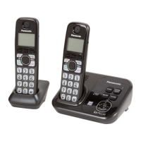
Lists accessories and packing materials for the KX-TG4732B.
Lists accessories and packing materials for the KX-TG4733B.
Lists accessories and packing materials for the KX-TG4734B.
Lists accessories and packing materials for the KX-TGA470B.
Lists replacement parts for the base unit.
Lists cabinet and electrical parts for the base unit.
Lists main PCB parts for the base unit.
Lists operational PCB parts for the base unit.
Lists replacement parts for the handset.
Lists cabinet and electrical parts for the handset.
Lists main PCB parts for the handset.
Lists LED board parts for the handset.
Lists replacement parts for the charger unit.
Lists cabinet and electrical parts for the charger unit.
Lists main PCB parts for the charger unit.
Lists accessories and packing materials for various models.
Lists accessories and packing materials for the KX-TG4732B.
Lists accessories and packing materials for the KX-TG4733B.
Lists accessories and packing materials for the KX-TG4734B.
Lists accessories and packing materials for the KX-TGA470B.
Lists types of screws used in the product.
Lists required fixtures and tools for service.
| Type | DECT telephone |
|---|---|
| Intercom | Yes |
| Languages support | ENG, ESP |
| Phonebook capacity | 50 entries |
| Redial list capacity | 5 |
| Backlight color | White |
| Display diagonal | 1.8 \ |
| Frequency band | 1.9 GHz |
| Channels quantity | 60 channels |
| Mac compatibility | - |
| Ethernet LAN (RJ-45) ports | 0 |
| Mounting type | Desk |
| Product color | Black |
| Battery type | AAA |
| Standby time | 11 h |
| Battery technology | Nickel-Metal Hydride (NiMH) |
| Battery recharge time | 7 h |
| Number of batteries supported | 2 |
| Base weight | 210 g |
|---|---|
| Handset weight | 150 g |
| Base dimensions | 150 x 117 x 67 mm |
| Handset dimensions (WxDxH) | 54 x 34 x 174 mm |