14
KX-TG4732B/KX-TG4733B/KX-TG4734B/KX-TGA470B
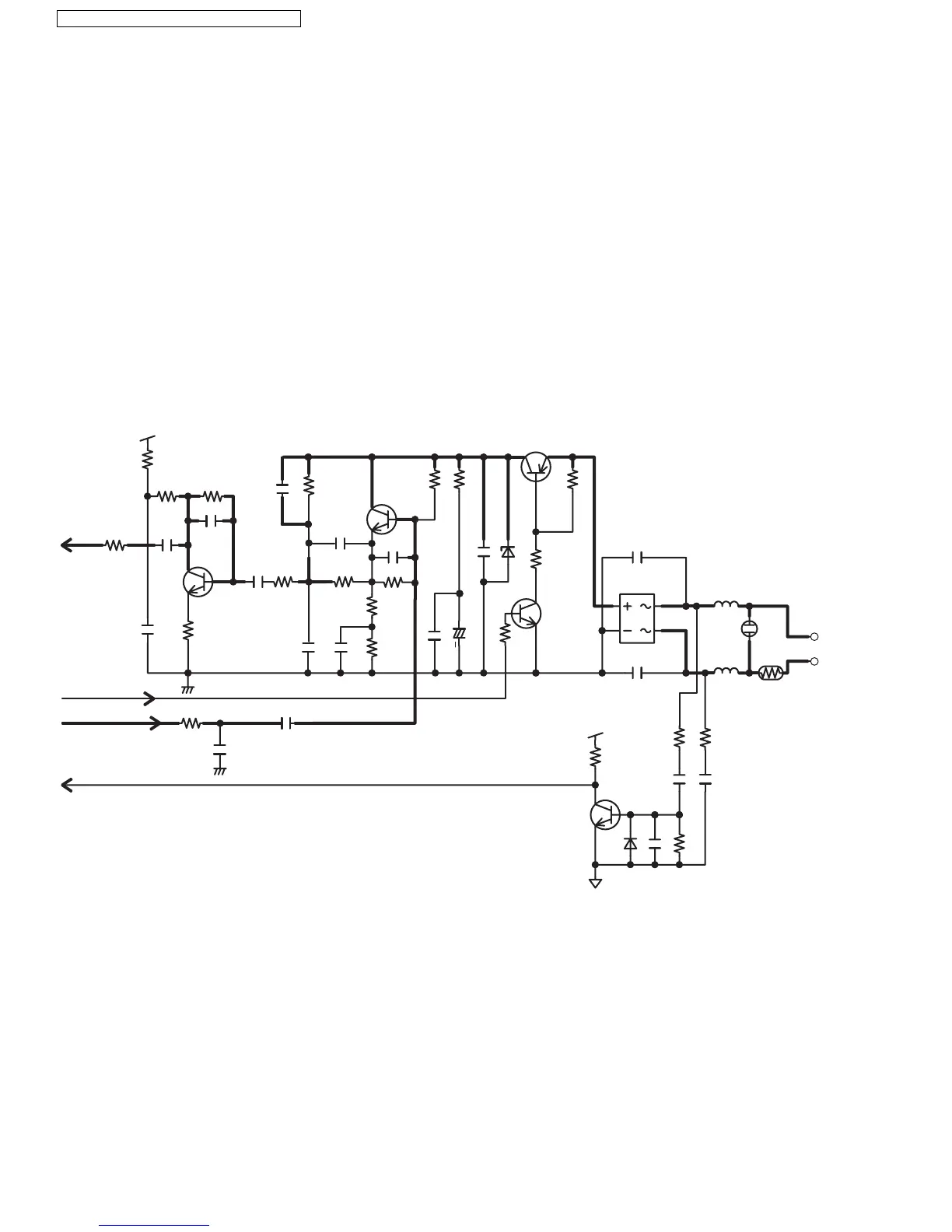
4.4.5. Telephone Line Interface
Telephone Line Interface Circuit:
Function
• Bell signal detection
• ON/OFF hook and pulse dial circuit
• Side tone circuit
Bell signal detection and OFF HOOK circuit:
In the idle mode, Q141 is open to cut the DC loop current and decrease the ring load. When ring voltage appears at the Tip (T)
and Ring (R) leads (When the telephone rings), the AC ring voltage is transferred as follows:
T → L101 → R111 → C111 → Q111 → BBIC pin 59
When the CPU (BBIC) detects a ring signal, Q141 turns on, thus providing an off-hook condition (active DC current flow through
the circuit). Following signal flow is the DC current flow.
T → L101 → D101 → Q141 → Q161 → R163 → R167 → D101 → L102 → P101 → R
ON HOOK Circuit:
Q141 is open, Q141 is connected as to cut the DC loop current and to cut the voice signal. The unit is consequently in an on-
hook condition.
Pulse Dial Circuit:
Pin 6 of BBIC turns Q141 ON/OFF to make the pulse dialing.
Side Tone Circuit:
Basically this circuit prevents the TX signal from feeding back to RX signal. As for this unit, TX signal feed back from Q161 is
canceled by the canceller circuit of BBIC.
3.0V
RX
Pin 16 of IC501
R176
R175
R178
C178
C175
Q171
R172
R171
+
Hook
Pin 6 of IC501
Pin 28 of IC501
Pin 59 of IC501
TX
BELL
C173
R165
C167
R163R167
C161
C142
D143
C168
C181
R160
R162
R145
R164
R177
Q161
C163
R161
Q142
Q141
R142
R141
R181 C184
C101
C102
D101
L101
L102
P101
SA101
L1T
L1R
TEL JACK
3.0V
R114
R111C111C113
D113
C112
R112
R113
Q111
3
4
2
1
C176
C171
C165
( )
C164
( )
( )
( )

 Loading...