66
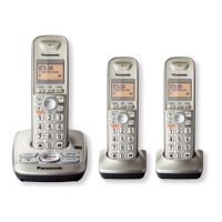
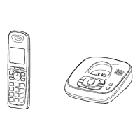
KX-TG4732B/KX-TG4733B/KX-TG4734B/KX-TGA470B
14 Schematic Diagram
14.1. For Schematic Diagram
14.1.1. Base Unit (Schematic Diagram (Base Unit_Main))
Notes:
1. DC voltage measurements are taken with voltmeter from the negative voltage line.
2. The schematic diagrams may be modified at any time with the development of new technology.
14.1.2. Handset (Schematic Diagram (Handset_Main))
Notes:
1. DC voltage measurements are taken with an oscilloscope or a tester with a ground.
2. The schematic diagrams may be modified at any time with the development of new technology.
14.1.3. Charger Unit (Schematic Diagram (Charger Unit))
Notes:
1. DC voltage measurements are taken with voltmeter from the negative voltage line.
2. The schematic diagrams may be modified at any time with the development of new technology.
Important Safety Notice:
Components identified by mark have special characteristics important for
safety. When replacing any of these components, use only the manufacture's
specified parts.
Important Safety Notice:
Components identified by mark have special characteristics important for
safety. When replacing any of these components, use only the manufacture's
specified parts.

 Loading...