21
KX-TG4732B/KX-TG4733B/KX-TG4734B/KX-TGA470B
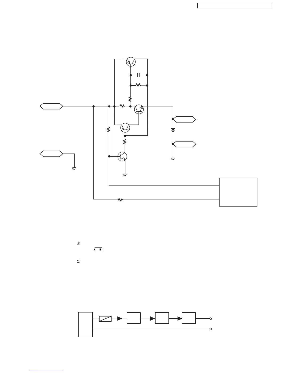
4.7.3. Charge Circuit
Circuit Operation:
When charging the handset on the Base Unit, the charge current is as follows;
DC+(6.5 V) → F301 → R371 → R372 →CHARGE+(Base) → CHARGE+(Handset) → Q4 → D7→ F1 → BATTERY+... Battery...
BATTERY- → R45 → GND → CHARGE-(Handset)→ CHARGE-(Base) → GND → DC-(GND)
In this way, the BBIC on Handset detects the fact that the battery is charged.
The charge current is controlled by switching Q9 of Handset.
Refer to Fig.101 in Power Supply Circuit/Reset Circuit (P.12).
4.7.4. Battery Low/Power Down Detector
Circuit Operation:
“Battery Low” and “Power Down” are detected by BBIC which check the voltage from battery.
The detected voltage is as follows;
• Battery Low
Battery voltage: V(Batt) 2.35 V ± 50 mV
The BBIC detects this level and " " starts flashing.
• Power Down
Battery voltage: V(Batt) 2.0 V ± 50 mV
The BBIC detects this level and power down.
4.7.5. Speakerphone
The hands-free loudspeaker at SP+ and SP- is used to generate the ring alarm.
4.8. Circuit Operation (Charger Unit)
Charge control is executed at handset side so that the operation when using charger is also controlled by handset.
Refer to Circuit Operation (Handset) (P.20)
The route for this is as follows: DC+pin of J1(+) → F1 → R1 → CHARGE+pad → Handset → CHARGE-pad → DC-pin of J1(-).
CHG +
Q4
R4
47K
R6
10K
Q9
GND
R7 CHG DET (34)
CHG CTRL (32)
100K
CHG -
GND
BATT +
BATTERY
2CELL
BATT +
GND
BBIC
IC1
Q2
R8
Q3
C27
R2
R9
R2R1
TP1
TP2
D1
J1
AC Adaptor
F1

 Loading...