22
KX-TG4221N/KX-TG4222N/KX-TG4223N/KX-TG313SK/KX-TG4224N/KX-TG4225N/KX-TGA421N
4.7.3. Charge Circuit
Circuit Operation:
When charging the handset on the Base Unit, the charge current is as follows;
DC+(5.5 V) F301 R371 R372 D362 CHARGE+(Base) CHARGE+(Handset) Q4 D7 F1 BATTERY+...
Battery...
BATTERY- R45 GND CHARGE-(Handset) CHARGE-(Base) GND DC-(GND)
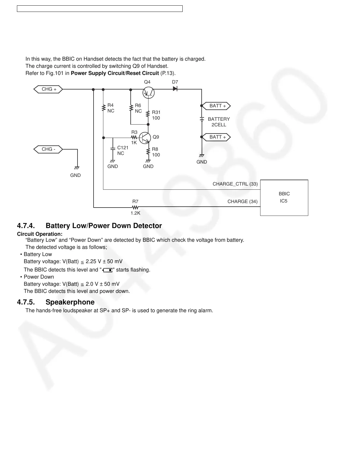
In this way, the BBIC on Handset detects the fact that the battery is charged.
The charge current is controlled by switching Q9 of Handset.
Refer to Fig.101 in Power Supply Circuit/Reset Circuit (P.13).
4.7.4. Battery Low/Power Down Detector
Circuit Operation:
“Battery Low” and “Power Down” are detected by BBIC which check the voltage from battery.
The detected voltage is as follows;
• Battery Low
Battery voltage: V(Batt) 2.25 V ± 50 mV
The BBIC detects this level and " " starts flashing.
• Power Down
Battery voltage: V(Batt) 2.0 V ± 50 mV
The BBIC detects this level and power down.
4.7.5. Speakerphone
The hands-free loudspeaker at SP+ and SP- is used to generate the ring alarm.
CHG +
Q4 D7
R3
1K
R31
100
R8
100
Q9
GND
R7 CHARGE (34)
CHARGE_CTRL (33)
1.2K
CHG -
GND
BATT +
BATTERY
2CELL
BATT +
GND
BBIC
IC5
R4
NC
R6
NC
GND
C121
NC

 Loading...