■Notes
1. Resistor
All the resistors are carbon 1/4W resistors, unless marked as follows.
The unit of resistance is an OHM [Ω] (K=1 000 M=1 000000).
: Nonflammable : Metal Oxide
: Solid : Metal Film
: Wire Wound : Fuse
2. Capacitor
: Temperature Compensation : Electrolytic
: Polyester : Bipolar
: Metalized Polyester : Dipped Tantalum
1. BLOCK DIAGRAM ・・・・・・・・・・・・・・・・・・・・・・・・・・・・・・・・・・
DIA-2
: Polypropylene : Z-Type
1.1. Signal Processing
3. Coil
The unit of inductance is a H, unless otherwise noted.
2. INTERCONNECTION BLOCK DIAGRAM ・・・・・・・・・・・・・・
DIA-3
4. Test Point
: Test Point
3. SCHEMATIC DIAGRAM ・・・・・・・・・・・・・・・・・・・・・・・・・・・・・
DIA-4
5. HOT and COLD indications
3.1. A -P.C.Board (1/3)
3.2. A -P.C.Board (2/3)
3.3. A -P.C.Board (3/3)
6. This schematic diagram is the latest at the time of printing and the subject to change without notice.
3.4. S / V / L -P.C.Board
■Precautions
4. CIRCUIT BOARDS DIAGRAM ・・・・・・・・・・・・・・・・・・・・・・・・
DIA-8
1. NEVER touch the HOT part or the HOT and COLD parts at the same time, or you may get an electric shock.
4.1. A -P.C.Board (Component Side)
2. NEVER short-circuit the HOT and COLD circuits, or the fuse may blow and the parts may break.
4.2. A -P.C.Board (Foil Side)
4.3. S / V / L -P.C.Board
4. MAKE SURE to unplug the power cord from the power outlet before removing the chassis.
5. When ordering parts, please check the part number of the "Replacement Parts List".
SECTION 4
< Schematic Diagram >
Components identified by the intemational symbol have special characteristics important for safety.
When replacing any of these components, use only the manufacturer's specified ones.
Model No.
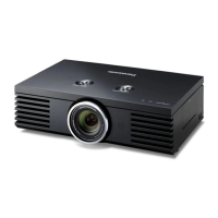
PT-AE7000U / AE7000EA / AE7000EH
The power circuit board contains a circuit area using a separate power supply to isolate the ground connection.
The circuit is defined by HOT and COLD indications in the schematic diagram. Take the precautions below:
3. NEVER connect an instrument such oscilloscope to the HOT and COLD circuit simultaneously, or the fuse may blow.
Connect the ground of instruments to the ground of the circuit being measured.
CONTENTS
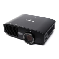
PT-AT5000E
Important Safety Notice
 Loading...
