Do you have a question about the Panasonic PT-AE7000U PT-AT5000E PT-AE700EA PT-AE7000EH and is the answer not in the manual?
General warnings about technician experience, electricity, and UV radiation.
Cautions regarding lithium battery replacement and projector use at high altitudes.
Technical details and handling advice for lead-free solder used in the projector.
Warning about potential radio interference and FCC compliance for Class B digital devices.
Safety rules for servicing, including no circuit modifications, power cord use, and isolation transformers.
Steps to measure and ensure leakage current is within safe limits to prevent shocks.
Cautions about UV radiation, high lamp pressure, and handling during servicing.
Details power supply, consumption, LCD panel size, aspect ratio, and display method.
Information on lamp type, operating environment (temp/humidity), and scanning frequencies.
Lists all input/output terminals and their signal specifications.
Specifications for the remote control, including power supply, operating range, and dimensions.
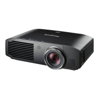
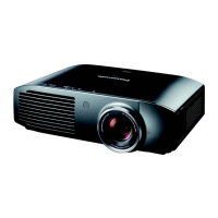
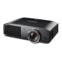
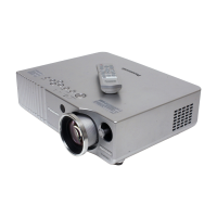
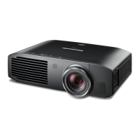
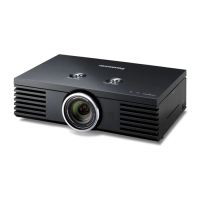
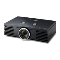
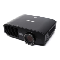
Identifies projector body, control panel, rear terminals, and remote control.
Details the projector's On-Screen Display menu structure and options.
Explains the service-specific EXT OPTION menu, including self-check and test patterns.
Covers serial connection, pin assignments, communication parameters, and control commands.
Provides guidance on LCD panels, lamp units, air filters, and general repair precautions.
Summarizes shutdown system causes, monitor LED indications, and presumed factors.
Identifies external parts like lens cover, air exhaust/intake ports, and indicators on the top/front.
Details security slot, connection terminals, AC IN, and adjustable feet on the back/bottom.
Explains the power button, input select, menu navigation, focus, and zoom controls.
Identifies computer, HDMI, and serial terminals on the projector's rear panel.
Describes the functions of the remote control buttons for picture, zoom, focus, and menu operations.
Details menu options for Picture Mode, Contrast, Brightness, Colour, Tint, etc., for different inputs.
Covers Aspect ratio, Keystone, Over Scan, and other display adjustments across various inputs.
Explains language selection, screen size, 3D input format, and brightness settings.
Details lens memory, auto switching, and function button assignments.
Procedure to open and close the service-specific EXT OPTION menu.
Explains Fan Full Mode, Auto Setup, Self Check, Status, and Flicker Adjust functions.
Details self-check items like software versions, input signals, fan/iris/lamp status, and usage time.
Instructions to enter the flicker adjustment mode, noting its use after part replacement.
Illustrates connection setup and provides pin assignments for RS-232C serial interface.
Defines communication parameters (baud rate, parity) and cable specifications for RS-232C.
Describes the standard STX, Command, Parameter, EXT format for PC control.
Lists commands for power, input switching, menu control, picture adjustments, and more.
Details commands for lens memory, trigger settings, and inquiry commands for status.
Notes on LCD panel pixel behavior and safety during lamp unit replacement.
Information on cleaning and replacing the air filter unit to prevent overheating.
Safety guidelines for repair, including eye protection, power disconnection, and static electricity.
Outlines service policies like block replacement and individual parts supply.
Procedures for replacing A-P.C.Board, data transfer, and identifying optical block types.
Guidance on when to replace consumable parts, specifically the lamp unit based on usage hours.
Step-by-step instructions for safely removing and installing a new lamp unit.
Instructions on how to reset the lamp usage timer after replacing the lamp unit.
Explains how dust accumulation affects performance and automatic power-off.
Procedures for cleaning the air filter unit and replacing the air filter kit.
Details monitor LED indications, shutdown detections, presumed factors, and OSD warnings.
Lists section contents for parts location and disassembly instructions.
Identifies the location of electrical components on PC boards and fan assemblies.
Provides a flowchart and general instructions for safely disassembling the projector.
Identifies specific boards (A, S, V, M2, etc.) and their functions.
Identifies various fans within the projector, such as exhaust, intake, and lamp fans.
Presents a flowchart for disassembly, starting with top cover removal.
Lists the order of component removal, including PC boards, optical block, and iris unit.
Step-by-step guide on how to remove the projector's top cover.
Instructions for unscrewing and removing the A-P.C.Board assembly.
Steps to remove the lamp unit and the V-P.C.Board.
Procedure for carefully removing the optical block assembly.
Steps for removing the analysis block, noting the incidence polarizer.
Instructions for removing the LED cover and L-P.C.Board.
Steps to remove the intake duct and M3 P.C.Board.
Procedures for removing the PBS array, integrator hold spring, and iris unit.
Steps to remove the lamp unit, lamp house, P-P.C.Board, and B-P.C.Board.
Instructions for removing the lamp socket and ballast block.
Steps for unscrewing and removing the P-P.C.Board.
Procedure for removing the B-P.C.Board, including notes on fan installation.
Steps to remove the lamp house and lamp duct base.
Instructions for removing the K-P.C.Board assembly containing K1 and K2 boards.
Steps for removing the front cover and adjuster leg.
Instructions for removing the bottom cover and M1-P.C.Board.
Lists adjustment items: Flicker, Data Transfer, Model Info Setup, Clog Sensor Calibration.
Outlines the procedure for updating microprocessor software via serial connection.
Step-by-step guide for adjusting flicker using the EXT OPTION menu.
Lists required equipment (PC, cable) and preparation steps for data transfer.
Instructions for backing up projector data using the service software.
Steps for restoring backed-up data after an A-P.C.Board replacement.
Lists equipment and preparation steps for model information setup.
Procedure to select and set the applicable model information via service software.
Lists equipment and preparation steps for serial number setup.
Procedure to input and send the product serial number using the service software.
Lists equipment, preparation, and environmental checks for clog sensor calibration.
Steps for performing clog sensor calibration, including altitude settings and progress monitoring.
Lists equipment and preparation steps for microprocessor software update.
Procedure for selecting serial port, model, CPU, and loading software for update.
Steps to click SOFT UPDATE, confirm, and monitor the update progress.
Instructions to click OK after completion and reboot projector to verify software version.
Lists contents: Block Diagram, Interconnection Diagram, Schematic Diagrams, Circuit Boards Diagrams.
Shows the overall block diagram and signal processing flow.
Illustrates how different PCBs and components are interconnected.
Details the signal path from input terminals to LCD panels.
Shows connections between main PC boards (A, V, H, L, K, P, B, M) and optical block.
Details input terminals, power regulators, and initial processing circuits.
Shows microprocessor, memory, and control interface circuitry.
Details FPGA, resize circuits, and DDR SDRAM connections.
Shows circuitry for color unevenness correction and frame creation.
Details the LCD panel controller and LVDS interface circuitry.
Shows the circuit diagram for the S-P.C.Board, including button inputs.
Details the circuit diagram for the V-P.C.Board, including LED and temperature sensor circuits.
Shows the circuit diagram for the L-P.C.Board, including LED and power connections.
Illustrates the physical placement of components on the A-P.C.Board's component side.
Shows the physical layout of traces and pads on the A-P.C.Board's foil side.
Detailed view of the PCB traces on the foil side of the A-P.C.Board.
Component and foil side layouts for the S-P.C.Board.
Component and foil side layouts for the V-P.C.Board.
Component and foil side layouts for the L-P.C.Board.
Lists section contents for exploded views and replacement parts.
Visual diagrams showing the location of parts within the projector assembly.
Details the components included in the projector's packaging.
Comprehensive list of replacement parts with part numbers and descriptions.
Shows location of main chassis parts, M3, K1, K2, M1, S PC Boards, and fans.
Details locations of components like the V P.C.Board, power box cover, and dust sponges.
Shows the placement of B, P, and H PC Boards and associated components.
Details the location of L PC Board, lens cap assembly, and optical block parts.
Shows placement of top panel components, adjuster leg, and M2 PC Board.
Details the location of A PC Board, terminal cover, and related components.
Illustrates how the projector, remote, cables, and accessories are packed.
Lists mechanical parts like fans, adjusters, covers, lenses, and filters with part numbers.
Includes labels, model name plates, and first few capacitor/connector part numbers.
Lists part numbers for various cables (AC, internal) and connectors.
Details capacitor part numbers, types, tolerances, and voltage ratings.
Continues listing capacitor part numbers, types, tolerances, and voltage ratings.
Lists capacitor part numbers, types, tolerances, and voltage ratings.
Lists part numbers for integrated circuits (ICs) and EMI filters.
Details resistor part numbers, values, tolerances, and wattage.
Continues listing resistor part numbers, values, tolerances, and wattage.
Continues listing resistor part numbers, values, tolerances, and wattage.
Continues listing resistor part numbers, values, tolerances, and wattage.
Lists part numbers for switches, connectors, and terminals.
Lists part numbers for diodes, LEDs, crystals, and transistors.
Lists part numbers for main circuit boards (S, V, L, K1, K2).
Lists part numbers for AC inlet, cables, fuses, and switches.
Lists part number for the K2 circuit board.